 |
|
 07-06-2015, 03:46 PM
|
#141
|
|
Bus Crazy
Join Date: Nov 2011
Location: Sault Ste. Marie, Ontario
Posts: 1,793
Year: 1997
Coachwork: Thomas
Chassis: B3800 Short bus
Engine: T444E
Rated Cap: 36
|
Yeah, I'd say reread the past couple pages of this thread. The subject came up not too long ago. Start on page 10 and read through to the end since some ideas were refined and changed along the way. As mentioned previously, post 130 has an especially nice write-up.
|

|
|
|
07-06-2015, 03:54 PM
|
#142
|
|
Bus Nut
Join Date: Jun 2013
Location: West Lafayette, IN
Posts: 832
Year: 1999
Coachwork: Thomas
Engine: 3126
Rated Cap: 72
|
Thanks jazty, I have my bus hooked up this way except my AC ground using shore power. I thought I read that it should be grounded through shore power not to the bus in case of reverse polarity bootleg grounds, else you would have 115 vac on the skin of your bus. I guess if you are always checking you should be good.
I found Mike's first post and you are correct, I need to bond my chassis ground to my AC ground, that way I will be safe. Now I can use the switch that I want.
|
|
|
|
|
07-26-2015, 12:27 PM
|
#143
|
|
Skoolie
Join Date: Mar 2015
Posts: 231
|
I work in the communications industry, we bond every thing.
|
|
|
|
|
07-26-2015, 04:31 PM
|
#144
|
|
Bus Geek
Join Date: Mar 2011
Location: Houston, Texas
Posts: 8,462
Year: 1946
Coachwork: Chevrolet/Wayne
Chassis: 1- 1/2 ton
Engine: Cummins 4BT
Rated Cap: 15
|
 Electron dimwit here...please explain "bond" idea.
|
|
|
|
|
07-26-2015, 11:36 PM
|
#145
|
|
Bus Crazy
Join Date: Jan 2008
Location: Adirondack Mountains NY
Posts: 1,101
|
"Bond" is to connect electrically. In a load center, the bus bars may have a long screw that can be inserted to tie the bar to the metal enclosure, or there will be a screw on the enclosure with a metal tab that can be inserted into the buss bar like one of the wires.
Please note that when you are wiring a house, the load center with the main breaker is the main disconnecting means to isolate the house from the utility. The neutral and the safety grounds are always tied together at that location. You can usually see the white wires and the bare wires inserted into the same bus bars.
When you have a sub-panel that is fed off of one of the breakers in the main load center, the neutral should always be insulated from the safety ground. The bare safety ground wires go into one buss bar that is "bonded" to the sub-panel cabinet. The white neutral wires go into a second buss bar that is mounted on insulators. The second buss bar may not come with the load center, it may have to be purchased separately and installed when installing the load center.
Since a bus is not hard-wired to the utility, when on a shore line it is a sub-panel and should have an insulated neutral. The neutral and safety ground can be connected together when isolated from the utility and running on generator. Transfer switches designed for RVs have an extra pole to switch the neutral or ground that is not present in transfer switches made for residential or industrial standby generators.
The bus chassis should be connected to the safety ground but not to the neutral. Whether the shoreline safety ground is bonded to the neutral or not, any campground outlet should be checked for the reverse-polarity bootleg ground before plugging in. If the outlet is reverse polarity, both the neutral and the safety ground will be "hot" compared to the surface under the wheels.
Many people will wire their buses with the neutral and safety ground bonded together like they would when wiring a house with a single load center. It's their bus. This will usually work, but will not work at all if attempting to plug the shoreline into an outlet with ground-fault interruption protection.
__________________
Someone said "Making good decisions comes from experience, experience comes from bad decisions." I say there are three kinds of people: those who learn from their mistakes, those who learn from the mistakes of others, and those who never learn.
|
|
|
|
|
07-27-2015, 10:12 AM
|
#146
|
|
Bus Geek
Join Date: Mar 2011
Location: Houston, Texas
Posts: 8,462
Year: 1946
Coachwork: Chevrolet/Wayne
Chassis: 1- 1/2 ton
Engine: Cummins 4BT
Rated Cap: 15
|
Great info...many thanks --- Even if I will have to read it 6 or 8 times. Like I said...electrical dunce...but I gotta' get familiar with this stuff soon.
|
|
|
|
|
07-27-2015, 12:36 PM
|
#147
|
|
Bus Crazy
Join Date: Feb 2012
Location: Salt Lake City Utah
Posts: 1,635
Year: 2000
Chassis: Blue Bird
Engine: ISC 8.3
|
Quote:
Originally Posted by c_hasbeen

I work in the communications industry, we bond every thing.
|
While I agree 100% with Redbear's comment.. when I read this I thought of "bond, noun: a force or feeling that unites people; a common emotion or interest" (Oxford Dictionary). Get it? Communications industry.. supporting emotional bonding.. Maybe it was just an awful pun kind of day for me.
|
|
|
|
|
07-27-2015, 01:02 PM
|
#148
|
|
Mini-Skoolie
Join Date: May 2015
Location: Washington
Posts: 25
Year: 1993
Coachwork: Blue Bird
Chassis: International
Engine: DT466
|
While it is important to switch both the hot and the neutral when switching between power sources, there shouldn't be any need to switch grounds. You can connect the EGC from the shore power connection, the EGC from the inverter, the EGC going to your bus 120VAC distribution system, and the bus skin connection all together permanently, regardless of your power source.
(EGC = Equipment Ground Conductor = GREEN or BARE COPPER conductor = NOT the WHITE neutral wire.)
(The neutral wire should be bonded to the EGC AT the inverter and NOWHERE else.)
|
|
|
|
|
07-27-2015, 02:10 PM
|
#149
|
|
Skoolie
Join Date: Mar 2015
Posts: 231
|
Remember how important the electrical system is and how we all just grow accustomed to things being wired correctly and never think of what could happen if an electrical appliance or fixture fails and the easiest path to ground is through a person or pet.
IF an internal components of an appliance, HVAC, power tool, switch, or other electrical equipment has a fault it can energize the metal enclosure and create a touch danger (Line to case failure).
How much voltage does it take to be dangerous?
In a dry environment, 120 Volts through the human body hand to hand or hand to foot the resistance is around 1000 ohms.
What does that actually mean to you and I?
Ohm's law says
I=V/R or 120V/1000 = .120 or 120 mA
120 milli amperes does not sound like very much but it really is lethal.
3 mA = electrical sensation
1 mA = pain with tendency to let go
10 mA = clamp voltage and unable to let go
50 mA for .2 seconds = heart fibrillation or potential death
If you have all of your electrical appliances connected to the same ground reference point then the current from a failure to a low resistant ground and then trip the beaker.(you want to make sure you are not the easiest least resistant path for the current to flow)
lets say your microwave transformer shorted out and was sending current to the metal case, you touch it allow a path to a ground source through your body, either by touching the oven which has a good conductive path to the fuel storage thank which is bolted to the frame and making a great path to return to ground, you are now part of this electrical circuit. Same would be if your plugin in your shore line and something has shorted out and has created the line to case failure and now the body of your bus is hot, you are then part of the circuit.
Most power tools have a three prong power cord to provide an easy path back to trip the breaker by going to ground and not utilizing your body as part of this circuit.
This is why cutting the ground prong off a cord is not a good idea.
Bonding at a communication shelter site is making sure that every conductive piece of material is some how tied to the same ground. This avoids any difference in voltage potential between metal items during a power surge of component failure.
the numbers I used for this are from a training class I have taken, I did not make it up.
thanks
|
|
|
|
|
08-24-2015, 01:36 PM
|
#150
|
|
New Member
Join Date: Aug 2015
Posts: 4
|
Wiring for dummies
[QUOTE=jmsokol;111519]Yes, it is indeed a small world. I started writing my No~Shock~Zone blog because a few of my pro-sound buddies said they had been shocked from their tour bus, and nobody could answer why. I took on the project as an intellectual challenge and found that the majority of electricians and technicians didn't really understand the basic differences between bonding and grounding.
While designing the schematic for a high-current 3-light ground tester I discovered that a bootleg ground condition with the polarity reversed would not be detected by traditional methods, but would still appear to operate normally. However, the entire chassis of the gear would be energized to 120 volts with a low-impedance connection capable of supplying 20 or 30 amps of ground fault current. I named this mis-wired outlet condition an RPBG for Reverse Polarity Bootleg Ground, but had trouble getting the test gear manufacturers to believe that it operated as I described it. They claimed their test gear could discover an RPBG, but after building the test rig as I showed in my demonstration schematic, they all admitted they had never thought about this condition and had not included it in any of their testing or documentation.
I'm seeing the same sort of confusion from the generator manufacturers over the issue of Neutral-Ground bonding and why it's necessary for RV electrical systems, but not for home electrical systems. Seems like a very simple concept to me, which is why I came up with the Neutral-Ground bonding plug as a solution for using a portable inverter generator such as a Honda EU2000i for power their RV. I've had literally hundreds of emails from RV owners who've built and use my G-N bonding plug successfully, but none of these same generator manufacturers want to admit that it works. That's why forums such as this are so important to spreading this basic knowledge. For reference here's the link to my G-N bonding plug article.
Does anyone know of a ground up tutorial on wiring a Skoolie or could mike perhaps provide one. I'm a contractor from ca and know how to wire everything on the inside. What I'm looking for is a precise answer to how do I set up my exterior. I will be running a connection for shore power cut into the side of my bus. I will be setting up a battery bank with bus bars that I want to recharge from shore, alternator, generator, and solar but do not want to draw from the bank while on shore. Also looking at the tesla home battery unit as a bank alternative.
What I don't understand is the order and specificity of the wiring if you have time mike give me a run through from the point of shore connection to the breaker box I'll use inside. How would you do it.
|
|
|
|
|
08-25-2015, 02:47 PM
|
#151
|
|
Bus Crazy
Join Date: Feb 2012
Location: Salt Lake City Utah
Posts: 1,635
Year: 2000
Chassis: Blue Bird
Engine: ISC 8.3
|
Since there haven't been any other replies, I'll take a swing. Here's a block diagram for "some day." Protection devices (fuses, over-current/arc/ground-fault breakers) are omitted for clarity.
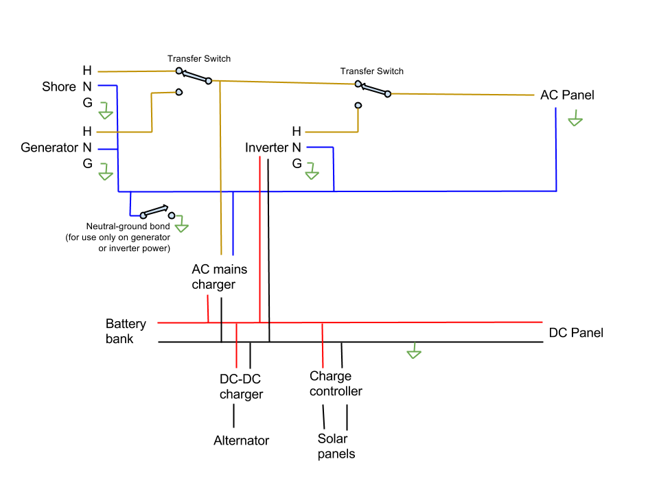
For now, my combined transfer switches and AC panel: an outlet strip. It plugs to the generator, inverter, or an extension cord as needed! When I get my roof raise and exterior changes done I'll begin wiring the interior and moving incrementally toward the "some day" ideal above.
Now, to your specific question about shore power. Some people simply have a cord with a male end wired into the bus; a compartment door is built somewhere so that the cord can be stowed and deployed from outside. That's how most RVs do it. Others use (or make) a regular extension cord and mount a marine style recessed male shore power connector in the exterior wall. In either case, you get to the point where there's a hot, neutral, and ground coming into the bus. Hot and neutral go to the AC distribution panel; ground goes to the bus chassis (and the panel ground bar is connected to the chassis too). That's about it for shore power. Choose a wire gauge for the shore power cord based on the power needs and length; add a second hot leg if you want to use 240 volts. The distribution panel in the bus is wired like any non-mobile sub-panel would be.
|
|
|
|
|
08-25-2015, 02:57 PM
|
#152
|
|
New Member
Join Date: Aug 2015
Posts: 4
|
Thank you that's exactly what I was looking for. Is there any way to ground the skin? Or a grounding plate like in electric forklifts or is it best to just keep it 100% isolated. For example would it help to bond a ground wire from the skin to the chassis??
|
|
|
|
|
08-25-2015, 03:03 PM
|
#153
|
|
Bus Crazy
Join Date: Feb 2012
Location: Salt Lake City Utah
Posts: 1,635
Year: 2000
Chassis: Blue Bird
Engine: ISC 8.3
|
I don't know about electric forklifts... but yes, the skin should be grounded. If yours is like mine, though, "the skin" is actually 20-30 separate pieces of sheet metal and it wouldn't be feasible to bond each of them. I'd just cross my fingers that there are enough rivets through each of them to the frame structure that somewhere there'll be a "good enough" electrical connection for each, and I'd bond the incoming grounding wire (groundING is the green one, isn't it? "groundED" is the neutral?) to convenient structure somewhere. Probably a rib in the wall, or the chair rail near the bottom of the wall.
|
|
|
|
|
08-25-2015, 03:26 PM
|
#154
|
|
Skoolie
Join Date: Mar 2010
Location: Texas
Posts: 218
Year: 1997
Coachwork: AmTran
Chassis: Genesis
Engine: DT466
Rated Cap: 84
|
Careful about putting a dc-dc charger in between the alternator and batteries. Alternators tend to use the batteries to smooth things out and further really hate being suddenly cut off from power output. What you want is a smart regulator such as from Balmar Voltage Regulators or the like.
|
|
|
|
|
08-25-2015, 03:42 PM
|
#155
|
|
Bus Crazy
Join Date: Feb 2012
Location: Salt Lake City Utah
Posts: 1,635
Year: 2000
Chassis: Blue Bird
Engine: ISC 8.3
|
Definitely good advice. I had contemplated that there'd be separate starting batteries, but didn't include them in the block diagram above. Those Balmar regulators are an interesting solution. Thanks for sharing!
|
|
|
|
|
08-26-2015, 01:36 PM
|
#156
|
|
Bus Geek
Join Date: Aug 2011
Location: Stony Plain Alberta Canada
Posts: 2,937
Year: 1992
Coachwork: Bluebird
Chassis: TC2000 FE
Engine: 190hp 5.9 Cummins
Rated Cap: 72
|
Remember to only ground the AC to your bus in a Single location.
As noted a few pages back, more than one AC ground point can cause issues.
Nat
__________________
"Don't argue with stupid people. They will just drag you down to their level, and beat you up with experience."
Patently waiting for the apocalypses to level the playing field in this physiological game of life commonly known as Civilization
|
|
|
|
|
02-03-2016, 02:02 PM
|
#157
|
|
Mini-Skoolie
Join Date: Feb 2016
Location: Atlanta
Posts: 19
Year: 1988
Coachwork: Chevrolet
Engine: 8.2L Detroit Diesel
Rated Cap: 35p
|
Quote:
Originally Posted by family wagon
Since there haven't been any other replies, I'll take a swing. Here's a block diagram for "some day." Protection devices (fuses, over-current/arc/ground-fault breakers) are omitted for clarity.

For now, my combined transfer switches and AC panel: an outlet strip. It plugs to the generator, inverter, or an extension cord as needed! When I get my roof raise and exterior changes done I'll begin wiring the interior and moving incrementally toward the "some day" ideal above.
Now, to your specific question about shore power. Some people simply have a cord with a male end wired into the bus; a compartment door is built somewhere so that the cord can be stowed and deployed from outside. That's how most RVs do it. Others use (or make) a regular extension cord and mount a marine style recessed male shore power connector in the exterior wall. In either case, you get to the point where there's a hot, neutral, and ground coming into the bus. Hot and neutral go to the AC distribution panel; ground goes to the bus chassis (and the panel ground bar is connected to the chassis too). That's about it for shore power. Choose a wire gauge for the shore power cord based on the power needs and length; add a second hot leg if you want to use 240 volts. The distribution panel in the bus is wired like any non-mobile sub-panel would be. |
would you mind terribly doing a diagram that overlays the things you omitted: fuses, breakers, anything else you'd consider etc. This has been the most comprehensive diagram for what I want to do, and now I'm just curious where those additional elements would fall.
also, if it's worth noting, i won't be using a solar panel at all, so the three ways that i intend to power are: generator, shore, alternator. the generator would go through the inverter to charge up the battery banks, right? (for if there isn't shore power or alternator to charge them)
|
|
|
|
|
07-26-2016, 12:59 PM
|
#158
|
|
Skoolie
Join Date: Apr 2015
Posts: 205
|
QUOTE=family wagon;121694]Since there haven't been any other replies, I'll take a swing. Here's a block diagram for "some day." Protection devices (fuses, over-current/arc/ground-fault breakers) are omitted for clarity.
[/QUOTE]
Thank you so very much for the diagram. Seeing the system laid out in this manner sure cleared up a LOT of stuff for me.
Quote:
Originally Posted by family wagon
For now, my combined transfer switches and AC panel: an outlet strip. It plugs to the generator, inverter, or an extension cord as needed! When I get my roof raise and exterior changes done I'll begin wiring the interior and moving incrementally toward the "some day" ideal above.
|
I have questions.
1. In the diagram above you showed TWO "transfer switches", not counting the one at the generator. As I read this diagram, it appears these are fairly simple a/b sort of switches having a center OFF position which will allow the selection of which source for hot (black wire) 110VAC will be used to feed the the HOT bus in the AC panel.
I've been looking at power transfer switches, and apart from being expensive, they seem to be a lot more than what the job calls for especially because we are only breaking the hot wire and not doing anything with the common or the safety ground.
Could someone suggest a simple, and hopefully cheap manual switch that will do this job? I'm thinking if I label everything clearly I should have no problems running this system.
Question 2 ... Unless you are talking about manually plugging and unplugging the various extensions cords, I really do not understand you comments about using a outlet strip as transfer switches and AC panel.
In any event ...thank you again for this extremely useful diagram.
|
|
|
|
|
07-26-2016, 03:27 PM
|
#159
|
|
Bus Crazy
Join Date: Feb 2012
Location: Salt Lake City Utah
Posts: 1,635
Year: 2000
Chassis: Blue Bird
Engine: ISC 8.3
|
Quote:
Originally Posted by Tedd
1. In the diagram above you showed TWO "transfer switches", not counting the one at the generator. As I read this diagram, it appears these are fairly simple a/b sort of switches having a center OFF position which will allow the selection of which source for hot (black wire) 110VAC will be used to feed the the HOT bus in the AC panel.
I've been looking at power transfer switches, and apart from being expensive, they seem to be a lot more than what the job calls for especially because we are only breaking the hot wire and not doing anything with the common or the safety ground.
Could someone suggest a simple, and hopefully cheap manual switch that will do this job? I'm thinking if I label everything clearly I should have no problems running this system.
|
Depends on how much power you want to switch. Also, center-off isn't required (but doesn't hurt). Here are some ideas:
- 120 V, 20 A max: Leviton 3-way switch under the covers, it's just a glorified single-pole double-throw switch. Note that this is the commercial version; the cheaper residential version is a 15 A switch.
- 120 V, 30 A max: DPDT relay Incidentally, several of the Amazon reviews mention they're using this relay to build a DIY transfer switch... You can make it automatic by wiring the coil to one of the incoming supplies, or you can make it manual by using a smaller SPDT switch so that the coil can be powered by either incoming supply.
A 240 V system could be done similarly, but DPDT switches (also called Form "C") would be needed.
Quote:
Originally Posted by Tedd
Question 2 ... Unless you are talking about manually plugging and unplugging the various extensions cords, I really do not understand you comments about using a outlet strip as transfer switches and AC panel.
|
Yep.. that's exactly what was meant. It's a self-documenting control system that virtually anybody can operate and diagnose.  
|
|
|
|
|
09-04-2016, 11:47 AM
|
#160
|
|
Skoolie
Join Date: Apr 2015
Posts: 205
|
HEY FAMILY WAGON,
I discussed adding a 2nd inverter to your diagram. Is this correct? (My up date uses a red pen for the hot 110VAC and switch add on:

|
|
|
|
|
|
| Thread Tools |
|
|
| Display Modes |
 Linear Mode Linear Mode
|
 Posting Rules
|
You may not post new threads
You may not post replies
You may not post attachments
You may not edit your posts
HTML code is Off
|
|
|
 Similar Threads
|
| Thread |
Thread Starter |
Forum |
Replies |
Last Post |
|
Bus Electrical Systems - DC
|
Les Lampman |
Conversion Tutorials and How-to's |
65 |
12-13-2016 05:49 AM |
|
Leveling systems
|
lornaschinske |
Conversion General Discussions |
0 |
08-04-2012 10:42 AM |
|
Electrical Systems
|
noahyay |
Conversion General Discussions |
11 |
07-29-2005 05:43 AM |
|
Sewer Systems
|
Steve |
Conversion Tutorials and How-to's |
0 |
06-16-2004 12:31 PM |
|
|
» Recent Threads |
|
|
|
|
|
|
|
|
|
|
|
|
|
|
|
|
|
|
|
|
|
|
|
|
|
|
|
|
|
|
|
|
|
|
|
|
|


