 |
 05-20-2009, 09:39 PM
|
#1
|
|
Bus Nut
Join Date: Mar 2009
Posts: 280
Year: 1992
Coachwork: Thomas
Chassis: Ford B700
Engine: 5.9L Cummins
Rated Cap: 65
|
Inverter wiring, will this work??
I have started building a tailgating bus with alot of great tips and ideas from this site. As soon as I think I have the electrical figured out, it seems to get that more confusing and was hoping for a little guidance. It has a 30 amp shore to a 30 amp 5 breaker panel. There will be 2 seperate outlet circuits, one on each side of the bus, mainly a 26-32" LCD on each side, 1 direct TV box and 30 amp converter and that is really it. All wiring is Romex 10/2 w/ground. There will be a stub out for a future roof mount A/C. No microwave, refrige, stove etc. I may plug a portable A/C into one side from time to time but only when on shore or generator. All lights will be DC. My main concern is the stupid inverter hookup. It is a cheap 1000 watt/3000 peak with 3 standard outlets on the front which I figured to be somewhere around 8-10 amps max. I considered a subpanel but thought it would be stupid since my wiring, minus the A/C, can all be powered by the inverter and would be very redundant. Thought about the suicide plug to backfeed the circuit but dont think that is the greatest idea. This bus will only be used during football season so it doesnt have to be as foolproof as an RV that jumps from hookup to hookup.
My question is, can I put a normal household switch at the end of one of the circuits and wire the inverter into the switched side? Then when I want to use the inverter, I turn it on and flip the switch to backfeed the circuit and the panel?
What do you do with the converter to keep it from running off of the inverter? My thought to this was to put this on a switched outlet with the switch right next to the inverter switch so when one is on the other is off. Is this needed?
To stop the dummies from flipping the switches, it would be in a seperate enclosed compartment with the DC fuses and also have a simple lockout on the switch itself to keep anyone that gets into the compartment for whatever reason from accidently hitting it.
|

|

|
|
05-20-2009, 10:04 PM
|
#2
|
|
Bus Nut
Join Date: Feb 2008
Posts: 362
|
Re: Inverter wiring, will this work??
The easiest way to do this is as follows:
Where your shore power comes in, put an outlet.
Wire the output of your inverter to a second outlet. Your inverter should have all the outlets coming off the same internal source, so I would probably actually run 2 of its outputs into the 2nd outlet with them in parallel.
I would recommend using the NEMA L5-30 outlet and plug as it is capable of a full 30 amps of power.
Put a wire with a plug on it. Again, the NEMA L5-30 is a good choice. It is actually a twist lock connector, which is good.
The end of the wire should feed the panel, and the panel should feed everything else.
Put the converter on a specific breaker by itself. Label the breaker clearly.
On the outlet fed by the inverter, put a very clear label that says "hey stupid, turn off breaker #5" or whatever the number is. 
On the outlet fed by shore/generator, put a very clear label that says "hey stupid, turn breaker #5 back on".
This way, all your sources are clearly and safely isolated. You run no risk of frying your inverter by accidentally having shore/generator + inverter on at the same time.
Oh yeah, when you get the generator, you can either plug the shore power wire itself into the generator, or wire in an additional outlet marked generator just for that source.
hope this helps,
jim
|
|
|
|
|
05-20-2009, 10:41 PM
|
#3
|
|
Bus Crazy
Join Date: Jan 2008
Location: Adirondack Mountains NY
Posts: 1,101
|
Re: Inverter wiring, will this work??
I must admit I have carefully used a suicide plug in the past, and in an emergency situation might carefully do so again in the future. I also must admit that I 'occasionally' make mistakes, especially when I am tired. I think using a suicide plug as a matter of regular practice is not a good idea, especially if you are not the only one who occupies the bus.
Putting a backfeed cutoff switch is only a small step closer to sanity. If the shoreline is live, the inverter plug falls out and the switch gets turned on, you still have a killer in your hands. The advantage is that if the plug doesn't fall out, and the switch is accidentally turned on by a curious guest or when you are tired, the sudden damage is less likely to be to humans. Also, the pins on the shoreline feed will be hot if you forget to kill the main breaker.
You really don't want to backfeed the whole bus AC system, anyway, just the entertainment. How about this: Use four of the branch breakers to feed the roof A/C stub, an outlet for the portable A/C, and the converter. Wire the fifth breaker to an outlet next to the inverter. Wire the outlets going to the entertainment to a male plug at this location. When you are on shoreline, plug the entertainment feed into the breaker-fed outlet. When you are on battery, move the plug to an inverter outlet. Or use 3 circuits for the non-inverter loads, put outlets fed by two breakers here, and have two male plugs, one to feed each entertainment branch.
The 1000/3000 watt inverter will provide about 8.3 amps continuous and 25 amps surge. The outlet devices will support up to at least 15 amps, unless they are fused for less. If the neutral pin is "T" shaped, then the outlets devices are rated to support 20 amp plugs.
Can your idea work? Yes, it can. Is it advisable? No.
By the way, #10 wire for branch circuits is overkill (unless you are using it because you got it for free). #12 wire is rated for 20 amps, and # 14 is rated for 15 amps. You only need #10 for the 30-amp shoreline. The 30-amp converter will need #10 on the DC output, but not the AC input.
Oversized wire is good to prevent resistance loss and wires heating up, but putting a too-big wire onto terminals not designed for it may cause mechanical stress and poor or broken connections, defeating the purpose of the larger wire. #10 might not be too big, but I wouldn't try stuffing a #6 wire onto a common household wire terminal.
__________________
Someone said "Making good decisions comes from experience, experience comes from bad decisions." I say there are three kinds of people: those who learn from their mistakes, those who learn from the mistakes of others, and those who never learn.
|
|
|
|
|
05-20-2009, 10:50 PM
|
#4
|
|
Bus Nut
Join Date: Mar 2007
Location: Northern BC Canada
Posts: 538
|
Re: Inverter wiring, will this work??
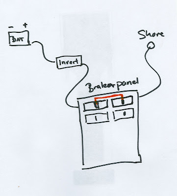
what badpuppy said, but in addition i would put the 2 brakers oposite each other and tie them together. Regular brakers have a hole on the switch so you can gang them together with a pin, so if you put them opposite each other and connect them then you can not turn one on without turning the other one off.
Here a quick drawing of what i mean.
|
|
|
|
|
05-21-2009, 04:31 PM
|
#5
|
|
Bus Nut
Join Date: Mar 2009
Posts: 280
Year: 1992
Coachwork: Thomas
Chassis: Ford B700
Engine: 5.9L Cummins
Rated Cap: 65
|
Re: Inverter wiring, will this work??
Originally the inverter was going to be wired into its own breaker like the picture shows but the dummies would have access to the panel and some idiot would flip the breaker trying to turn on the outside light or something. The breakers are horizontally stacked and cant be locked together and there is also no cover over the panel, it is out of a camper or this would be choice #1.
I like the plug idea, its similar to my suicide plug into the wall but a heck of alot better! Im a little slow at times so bear with me, I would put a female outlet (that is fed by the inverter) right next to the male shore inlet. Then run a jumper plug between the two when I want the inverter and no gen plugged into it? That would be a tough one for a drunk friend to screw up! How would you wire 2 outlets on the inverter in parrallel to the outlet? I was a little concerned on using only 1 of them with 3 being on it as I don't want to overheat the outlet. They are all 15 amp style outlets on the inverter, not the 20.
For the 10/2 wire, I did buy it but it was leftover and cheap otherwise I would have used a little smaller gauge or SO cable. Its funny how the mind works sometimes, I have 50' of Romex and have been trying to design the entire AC system around this to avoid buying another 20', yet I had no problem spending $75 to replace all of the rubber on the windows so it looks nice and clean with the new tint and using mulitple $15 tubes of 5200....on the interior
As far as my switch idea, considering it is a perfect world and noone ever screws up, I take it that it would work? I dont really care if the inverter gets burnt up on accident just as long as I can realize it before it catches fire, if that would happen. To clarify, this switch would be hardwired with the opposing male end plugged into the inverter which I would tie in place so it would not fall out.
|
|
|
|
|
05-21-2009, 04:38 PM
|
#6
|
|
Bus Nut
Join Date: Mar 2009
Posts: 280
Year: 1992
Coachwork: Thomas
Chassis: Ford B700
Engine: 5.9L Cummins
Rated Cap: 65
|
Re: Inverter wiring, will this work??
Here is the bus building pics in case you are interested. Ill post some in the gallery this weekend.
http://s626.photobucket.com/albums/tt34 ... s/?start=0
|
|
|
|
|
05-21-2009, 06:58 PM
|
#7
|
|
Bus Nut
Join Date: Feb 2008
Posts: 362
|
Re: Inverter wiring, will this work??
ok, I've re-thought my suggestion, and I don't think it addresses your needs well enough.
So, I have an alternate suggestion... maybe this will be better, maybe not.
Currently you have 30A shore line connected to a breaker box, which feeds up to 5 (4 plus main?) circuits.
For generator, you can just plug the shore power wire into the generator and be good to go. Of course, you might need an adapter for that.
That only leaves the switching from inverter to/from shore/generator to deal with.
So my suggestion is to take 2 of your breaker protected circuits, and bring them out of the box to 2 different outlets right beside the box. Label them something like "street side" and "curb side", just so that they match. That is the entire circuit for those 2 circuits.
For connecting the circuits to the outlets down the indicated side, use extension cord wire rather than solid romex if you can, at least for the first section. I recommend 12-2 w/ground or better, just to be safe. Keep a standard 15/20 amp plug on the end near the breaker box. Label one "street side" and the other "curb side", keeping things matching.
On the inverter, label one outlet "street side" and the other "curb side".
To switch a circuit from shore/generator, simply move the plug from the breaker fed outlet to an outlet on the inverter. To switch it back, just move the wire back. This assumes the inverter is near the breaker box. If not, just move the outlet boxes fed from the breaker box to be beside the inverter.
The inverter will do its best to protect itself from over current situations. The breaker box will protect everything else when fed by shore or generator.
I believe this will do what you need. Basically, you're ensuring that each of those circuits can only be connected to 1 source at a time. You could even have 1 circuit on the inverter while everything else is on shore or generator.
I don't have a drawing program on my mac, or I'd draw it out and make it a bit clearer.
hope this helps,
jim
|
|
|
|
|
05-21-2009, 07:18 PM
|
#8
|
|
Bus Crazy
Join Date: Jan 2008
Location: Adirondack Mountains NY
Posts: 1,101
|
Re: Inverter wiring, will this work??
I did get your switch explanation correctly. I'm glad you will tie the plug in. If you do that, it would be even better to connect the wire inside the case.
I haven't got the hang of using the gallery to put something in a post. To see what I was describing, go here:
http://www.skoolie.net/gallery2/v/Sk...r+transfer.jpg
You plug the shoreline into the grid or a genny if available, using any adapters that might be needed.
On external power, the plugs feeding the right and left entertainment outlets plug into the feeder outlets powered by the circuit breakers.
On battery, you plug one or both sides into the inverter, and manage your loads to keep within the inverter ratings.
There is no possible way to have killer hot male plugs either inside the bus, or outside at the shoreline input. Also, the converter will never draw from the inverter.
(Although they do say if you make something idiot proof, they will build a better idiot!  )
__________________
Someone said "Making good decisions comes from experience, experience comes from bad decisions." I say there are three kinds of people: those who learn from their mistakes, those who learn from the mistakes of others, and those who never learn.
|
|
|
|
|
05-21-2009, 09:00 PM
|
#9
|
|
Bus Nut
Join Date: Mar 2009
Posts: 280
Year: 1992
Coachwork: Thomas
Chassis: Ford B700
Engine: 5.9L Cummins
Rated Cap: 65
|
Re: Inverter wiring, will this work??
Thanks for the drawing, that is another good idea, I will have to stew over it all... I guess no takers on my switch idea, I thought it was pure genious at the time lol. Another question. Ill figure the picture thing out and post the final schematic tomorrow night.
On the DC side of things again trying to keep it simplified. Plan A was to run a heavy gauge wire from the batt through an ANL fuse into the cabin then into a master disconnect switch so I could simply cutoff all interior DC power and still have power to run the bus. From there into a single post/stud. Off of this same post I will branch off into a seperate needs: blade style fuse holder for small circuits i.e. lights, radio, water pump, converter output on this post, 2 amps and the inverter. Do you forsee any problems running the converter and inverter into the same DC post? Do I need to fuse again after the post and before the inverter, do you need to fuse the output of the converter also?
Plan A (all lights will have integrated on/off switches)
Batts > 1x1 ANL > Master Dis (inside) > Post > Inverter
> Fuse dist block> Amps
< Converter
> Fuse Panel > Lights 1, lights 2, radio, water pump, rope lighting
Plan B
Batts> 1x2 ANL > Side 1 > Post 1> Inverter
> Side 2 Post 2< Converter
> Fuse Block > Amps
> Fuse Panel
Plan B was to run a 1x2 ANL holder and branch to 2 posts, 1 for converter/small circuits, amps and another to the inverter which would alow me to run 2 different size ANL fuses which may be more apporpriate. This would put my master disconnect into the factory battery box which has little to no room.
For this setup on dual batteries, I assume the batteries would equalize themselves if you ran it all off of batt A that has jumpers between A&B or would you run say pos off batt A and neg off batt B to help equalize.
Also, how do you determine the size fuse needed? Do you add the max amps drawn on the circuit and go as close to that as possible, or go larger/smaller?
|
|
|
|
|
05-26-2009, 08:14 PM
|
#10
|
|
Bus Crazy
Join Date: Jan 2008
Location: Adirondack Mountains NY
Posts: 1,101
|
Re: Inverter wiring, will this work??
Fuse sizes are chosen by what you are protecting:
1. Protecting wires from shorts
2. Minimizing damage from failed equipment to itself
3. Minimizing damage from runaway equipment to other equipment
The inverter and converter should have fuses or other overcurrent protection built into them. If not, you would want to fuse the inputs and outputs where they connect to your own wiring. That would be your case "B" regarding the inverter. If the inverter has a DC input fuse or breaker, then "B" is unnecessary.
In "A" the ANL fuse (as close to the battery as possible) should be the sized for the ampacity of the wire going to the switch, post, and power panel input. You never want to blow this fuse unless someone drops a wrench between the post or switch and ground, or some drunk crashes into the side of the bus and drives a piece of body metal through the battery wire insulation.
The DC branch circuit fuses can be sized for ampacity, also. That's how house wiring is done. 15 amps for #14 wire, 20 amps for #12, and 30 amps for #10. If you have a delicate low-power device on a dedicated circuit, you may want "just enough" to power it. In many cases there will be an internal fuse, so no problem. If not, check the owner's manual for the device.
If you still have to guess, remember you don't want the fuse to blow on start-ups or hiccups, only problems. I would probably double the measured power draw. For example, if a radio draws a steady 2-3 amps in use, there are probably fluctiations you can't measure with an everyday meter. I would use a 5-amp slow-blow or 10-amp fast blow fuse for that. Motor applications may draw 3 to 5 times the running current during start-up. Someone else will have to chime in if they have a good rule of thumb for motor fuses.
I don't see a disconnect in "B," but from the description it would be between the battery and 2 ANL fuses, and serve the same function as in "A." Just remember in both cases, if you turn the master switch off when on shoreline, the converter
won't recharge the batteries. That doesn't mean it's a bad plan, because the switch does what it is supposed to - save the batteries from being drained when the bus is parked and not in use.
As far as parallel battery pack wiring, it's done both ways. The problem is a bad jumper connection will make one battery do all the work, regardless of which way you connect them. I myself prefer the ground at one end of the battery pack, and the positive on the other end, just to equalize the trace of resistance found in the wires. If one of the jumpers has a bad connection, however, you're still only working off of part of the bank.
__________________
Someone said "Making good decisions comes from experience, experience comes from bad decisions." I say there are three kinds of people: those who learn from their mistakes, those who learn from the mistakes of others, and those who never learn.
|
|
|
|
|
05-26-2009, 09:45 PM
|
#11
|
|
Bus Nut
Join Date: Mar 2009
Posts: 280
Year: 1992
Coachwork: Thomas
Chassis: Ford B700
Engine: 5.9L Cummins
Rated Cap: 65
|
Re: Inverter wiring, will this work??
So as long as I properly fuse everything and use the correct gauge wire then my plan A with one battery lead to the post and everything running off of the single stud would work?
Is there any issues with using too large a gauge wire? I learned my lesson on voltage drop on landscape lighting after I ran wires and poured a driveway over them and would rather not repeat it. I have a spool of 12g auto wire that I wanted to run my DC light circuits off of ( about 5 lights per circuit @ roughly 8 watts ea is my estimate) and also for the taillight wire extensions.
I also took everyones advice on the male pigtail out of the breaker box. Its alot better than my original plan. Thanks for all of your help with this.
|
|
|
|
|
05-26-2009, 11:23 PM
|
#12
|
|
Bus Crazy
Join Date: Jan 2008
Location: Adirondack Mountains NY
Posts: 1,101
|
Re: Inverter wiring, will this work??
The issue with too small a wire is its resistance - at high current flows it heats up, wasting some of the desired energy as heat. In extreme situations it could cause a fire hazard. Since power (watts) = volts x amps, at low voltage more current is needed to get the same power. 1200 watts is 10 amps at 120 volts, and 100 amps at 12 volts.
The issue with too large a wire is purely mechanical - supporting its weight, routing it, and making proper connections - ever tried to put #6 wire into a connector designed for #10? Done badly, this could become a high resistance point instead. With the proper support, routing and connection, larger wire is good.
You can figure out your wiring needs by adding up the power draw. Changing the equation around to amps = watts/volts, each 8 watt lamp draws 8/12 or 0.67 of an amp. #12 wire can support 20 amps at normal distances and temperatures.
__________________
Someone said "Making good decisions comes from experience, experience comes from bad decisions." I say there are three kinds of people: those who learn from their mistakes, those who learn from the mistakes of others, and those who never learn.
|
|
|
|
|
 Posting Rules
|
You may not post new threads
You may not post replies
You may not post attachments
You may not edit your posts
HTML code is Off
|
|
|
|
 » Recent Threads
 |
|
|
|
|
|
|
|
|
|
|
|
|
|
|
|
|
|
|
|
|
|
|
|
|
|
|
|
|
|
|
|
|
|
|
|
|
|


 Linear Mode

