 |
|
 05-02-2018, 11:05 AM
|
#21
|
|
Mini-Skoolie
Join Date: Nov 2017
Location: New Hampshire
Posts: 10
Year: 2007
Coachwork: Bluebird
Chassis: GMC Savana
|
New here.
Great start! I'll be following your build for ideas.
Any ideas on your layout yet?
Curios as to how people feel about the mileage.
Seem real high. Also 4 wheels and gas verses 6 wheels and Diesel?
Nice to be getting a bus in California with no rust! Here in NH not so lucky.
|

|

|
|
05-03-2018, 06:04 PM
|
#22
|
|
Bus Nut
Join Date: Apr 2018
Posts: 421
|
This is a very rough draft. The small bed on the right side actually consists of two seats, one facing forward and one facing back, with a table in the middle that lowers and turns it into a bed. The bathroom will have a composting head, and the counter space between the bathroom and master bed in the back is a kitchenette.


|
|
|
|
|
05-04-2018, 02:19 AM
|
#23
|
|
Bus Nut
Join Date: Apr 2018
Posts: 421
|
Quote:
Originally Posted by MovinOn

New here.
Great start! I'll be following your build for ideas.
Any ideas on your layout yet?
Curios as to how people feel about the mileage.
Seem real high. Also 4 wheels and gas verses 6 wheels and Diesel?
Nice to be getting a bus in California with no rust! Here in NH not so lucky.
|
I just picked up the bus from the mechanic today, and he was pretty jealous of the bus/engine combo--regardless of the mileage. Everything I've found online is that the pre-2003 7.3L Powerstroke engine is good for up to a million miles, which is more than I'll ever put on her over my lifetime.
Now, I am not a mechanic or a gearhead, but it seems to me that a 6 wheel diesel is preferable to a 4 wheel gas engine, but I'll leave that to someone else.
|
|
|
|
|
05-21-2018, 04:40 AM
|
#24
|
|
New Member
Join Date: Apr 2018
Location: Blaine MN
Posts: 4
Year: 1994
Chassis: Ford E350
Engine: 7.3 Diesel IDI
Rated Cap: 4 window Shorty
|
I have a 94 IDI that I THOUGHT was a powerstroke but still a good bus! Loving the writeups so far! I have a very similar bus! You will love the powerstroke just make sure you check the oil and coolant and let it warm up for a bit before you hammer on it! 
|
|
|
|
|
05-31-2018, 01:07 PM
|
#25
|
|
Mini-Skoolie
Join Date: Jan 2018
Posts: 21
|
If I'm not mistaken, the 2003 and earlier 7.3's were "labeled " powerstroke, but we're actually International Navistar engines. They are 1mil mile engines providing you P.M.'d them regularly. They were also used in the bigger International busses, but, the E350/450 turbos were underpowered and had an internal wastegate due to the inability to install the intercooler because of confined space, the earlier models and full sized busses had the cooler. Still, not gonna win at the track but it's a constant runner.
|
|
|
|
|
06-17-2018, 11:58 PM
|
#26
|
|
Bus Nut
Join Date: Apr 2018
Posts: 421
|
Maintenance Schedule for 7.3L Powerstroke
Here's what the mechanic said for my maintenance schedule:
Fuel Filter: every 10-15k miles
Oil Filter: every 3-5k miles
Trans Service: every 20k miles
Differential Service: every 30k miles
He was also pretty adamant that I should install a Cam Position Sensor (10mm head, 8mm thread), but since I'm not a mechanic type, all I could gather was that it would help kill the engine before something catastrophic happens. Anyone have an opinion on that?
|
|
|
|
|
06-18-2018, 10:50 AM
|
#27
|
|
Bus Crazy
Join Date: May 2010
Location: Farmington Hills, Mi (Detroit area)
Posts: 1,968
Year: 2000
Coachwork: Eldorado Aerotech 24'
Chassis: Ford E-450 Cutaway Bus
Engine: 7.3L Powerstroke
Rated Cap: 19
|
The CPS is a weak link in this engine. When it fails the engine can "hickup" repeatedly or die then restart or just die (like the key's been turned off). Failure won't damage the engine, just make you're life very interesting.
The new CPS parts are more reliable and fairly cheap, around $28. Not hard to install.
|
|
|
|
|
03-09-2019, 11:16 PM
|
#28
|
|
Bus Nut
Join Date: Apr 2018
Posts: 421
|
How to Build a Water Tank
So I finally got around to building my water tanks. I scored two 40 gallon tanks for $3 a piece at a liquidation sale, and here's my writeup for everything I discovered:
Installing Bulkheads:
This was a new area for me. There are a few tutorials on YouTube, but they all assume there's an easy opening in the tank (like a blue rain barrel for instance). My tanks were solid all the way around, so I had to cut a very large opening (which I would repair later) in order to get the inner part of the bulkheads inside the tank.
How many bulkhead fittings do you need? What size should they be? We need an inlet, a vent, an outlet, and a drain.
The standard size for inlet hoses is 1 1/4", so that's what I got for the fresh water inlet.
The standard size for the vent is 1/2", so that's what I got for the fresh water vent.
My water pump uses 1/2" lines, so I got a double-threaded bulkhead fitting (to use an elbow on the inside to draw water from the bottom of the tank)
The standard size for a drain is 3/4", so I got one with a ball valve to make it easy.
For the Grey Water Tank:
We need an inlet, a vent, and a drain. But what about an outlet? Well, I don't plan on having one. Normally, an outlet would be hooked up to a port for a pump out station, but since this is just grey water (dish water with biodegradable soap), I have no qualms dumping this in my driveway. It makes it a lot simpler too and saves space, but that's just me.
For the inlet, I wanted as big as possible (within reason) so that there would be no delay when the sink drains (or shower, if that goes in). So I went with a 2" bulkhead fitting, but in hindsight I wish I would've gone with the same as the freshwater tank so I could use that hose (now I have to buy an additional hose in the 2" size).
For the vent, I went with the standard 1/2" bulkhead fitting.
For the drain, I used the same as the freshwater tank (1/2").
To Recap:
Fresh Water Tank Bulkhead Fittings:
1 1/4" Inlet
1/2" Vent
1/2" Outlet
3/4" Drain
Grey Water Tank Bulkhead Fittings:
2" Inlet
1/2" Vent
3/4" Drain
I marked out the locations for all the bulkheads. The inlet and vent are nearby each other on top (since they eventually will lead to the same exterior port), near where the inlet hardware would be located, the outlet was at the bottom in one corner, and the drain was at the aft end on the bottom.
Next, find out the diameter of the largest bulkhead fitting. For me, on my freshwater tank, that's the 1 1/4" inlet, but the diameter of the interior fitting is larger than that--I found the hole saw that matched the size and used that. I drilled a hole on the "top" of the tank (in quotations, because it was arbitrary--I got to decide which side was up) and saved the cut out circle for later.
Next, I cut out all the bulkhead holes. This was a simple process--I matched up the bulkhead fitting size with the appropriate hole saw and cut it out, and discarded the circle cutouts.
Next, I tossed the vent bulkhead fitting in the largest hole, maneuvered it to its opening, and carefully pulled it through and installed the nut to hold it in place. This took me quite a few tries until I got it right.
I repeated this process with the outlet (be sure to install the interior elbow before hand if you're using it), the drain, and then finally the inlet.
And now the only hole that is left in the water tank is the hole you first cut that is the largest.
How to Repair a Hole in a Water Tank
I had no idea what I was doing for this step. I put a drill bit in the center of the circular plastic cut out that I saved from before and held this circle in place using that. Then, using the Poly Plastic Welder, I smushed one side of this and melted it back into place just enough to hold it steady. Then, using the plastic welding strips, I melted around the rest of the circle and touched up as necessary. This was not a pretty job, but it got the job done.
Once complete, the tank was whole again, with all the appropriate bulkhead fittings installed where they needed to be.
I repeated the same process for the grey water tank, using the different sized hole saws as applicable.


|
|
|
|
|
03-10-2019, 08:40 AM
|
#29
|
|
Bus Crazy
Join Date: May 2017
Location: Chattanooga, TN
Posts: 1,413
Year: 2001
Coachwork: Thomas
Chassis: Thomas
Engine: CAT 3126
|
Gray water sounds innocuous, but you may think 2x about dumping in your driveway after you get a smell of the super ripe stuff.
|
|
|
|
|
03-10-2019, 08:41 AM
|
#30
|
|
Bus Crazy
Join Date: May 2017
Location: Chattanooga, TN
Posts: 1,413
Year: 2001
Coachwork: Thomas
Chassis: Thomas
Engine: CAT 3126
|
All your plastic welding and unistrut work looks top notch!
|
|
|
|
|
03-10-2019, 10:07 PM
|
#31
|
|
Almost There
Join Date: Jun 2018
Location: Colorado
Posts: 93
Year: 2006
Coachwork: Collins
Chassis: Chevrolet
Engine: 6.6 LLY Duramax
Rated Cap: 15
|
Thank you for the pictures of the water tank support. How are you keeping the bolt heads holding the slotted angle metal off of the tank? What about abrasion?
|
|
|
|
|
03-10-2019, 10:34 PM
|
#32
|
|
Bus Nut
Join Date: Apr 2018
Posts: 421
|
Thanks, I only included pictures of the freshwater tank's welding, because that was my second go... the greywater tank, which was essentially my practice, is a little more brown and burned... oops.
How do people here feel about dumping greywater while out? Most of my excursions will be boondocking, and I really don't see any issues with just dumping my greywater wherever I am in the mountains (outside of any legal issues... I believe that's prohibited by law).
As for my methods of preventing abrasion and whatnot... well, I have none. I considered using the sheet metal I pulled off from the walls to create a safe cube, but I opted not to go that route for the time being because of two reasons.
1: I used carriage bolts, with a smooth head on the inside, to create the frame. While not eliminating abrasion, it seriously reduces it from, say, a regular hex bolt.
2. Using a grinder, I cut away the "hot spots" on the bus undercarriage that could potentially come in contact with the tank. For the freshwater tank, I had to cut off the sharp corners of two non-structural flanges on the outside wall, and shorten two bolts on the bus's frame. For the greywater tank, I just had to cut off one flange that supports the outside wall. These flanges are quite thin and flimsy, and while I'm sure they are useful, I am comfortable accepting the risk by removing a few inches.
A quick number 3: I succumbed to planning paralysis. If you look at my post history, I haven't made any updates for something like 9 months. That was because I had to install these tanks to the floor before I could build the floor up. But I kept planning and planning and planning, and wanted to mount the tanks on an extended frame that attached to 3 struts, and essentially looked like an upside down bridge. But as I started working, I kept finding new things that I hadn't considered: the suspension got in the way, there's no way to install the frame fully formed, how the hell am I going to do this, etc... etc...
Finally I realized that this won't be perfect. There will be weak spots, and there may be failures in the future... but for my own sanity I had to accept "good enough" and start working.
Although I just installed the grey water tank today, and as I was finishing the last step, I realized there was an easier and more efficient and stronger way to install it... I'll probably regret it but, like I say at my day job, it's good enough for government work.
|
|
|
|
|
03-11-2019, 09:12 PM
|
#33
|
|
Almost There
Join Date: Jun 2018
Location: Colorado
Posts: 93
Year: 2006
Coachwork: Collins
Chassis: Chevrolet
Engine: 6.6 LLY Duramax
Rated Cap: 15
|
Thanks for explaining - makes sense to me.
|
|
|
|
|
03-12-2019, 06:50 PM
|
#34
|
|
Bus Crazy
Join Date: May 2017
Location: Chattanooga, TN
Posts: 1,413
Year: 2001
Coachwork: Thomas
Chassis: Thomas
Engine: CAT 3126
|
Re: paralysis by analysis: Sometimes the only way to get clarity is to move forward. Even if you have to stop and fix something.
As far as gray water, I never understood why it would be a big deal to dump it until I gained an appreciation for the bacteria.
In my experience it has smelled as bad or even worse than black water. One time I thought I would just crack the valve before a drive, but then wind blows it all over the underside of the bus.
Ive seen places that used to allow boondocking cite gray water dumping as the reason that they stopped allowing it.
Is it the worst thing in the world? No, but I make every effort to properly dump after a few stinky experiences.
|
|
|
|
|
03-24-2019, 11:11 AM
|
#35
|
|
Bus Nut
Join Date: Apr 2018
Posts: 421
|
How to Install a Dash Cam and Backup Camera
Here's my post on installing a dashcam and backup camera. I used the Pruveeo model that's available on amazon.
The Pruveeo model is pretty straight forward--plug it in to a cigarette lighter and the plug housing steps it down to 5v and voila, it works. But my cigarette lighter is hot, meaning it's always powered, even with the bus off--and I don't want to have to plug it in and out everytime, I want it automatic.
So what dash device is powered up with the bus? The radio of course.
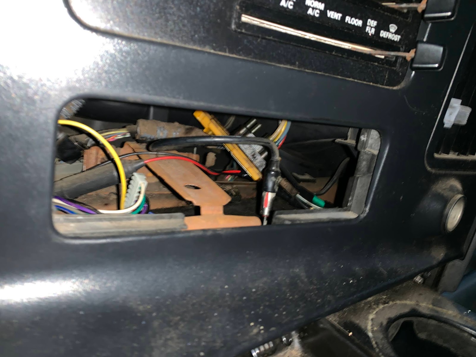
How to Power a Dash Cam and Backup Camera

I removed enough of the front dash (not all the way, though--careful not to break any of the snaps) to pull out the radio, and then pulled out its cord and discarded the radio unit itself. There are many wires that lead to the radio plug, so I removed all of them and stripped the red and black wire. I verified with the voltmeter that these wires only are powered when the bus is on.
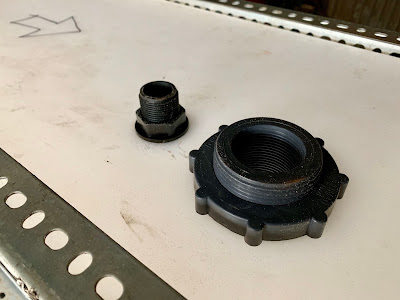
Next, you have to disassemble the adapter housing. You can't just cut the cord and attach it because the bus voltage is 12, and the dash cam accepts only 5v. So I disassembled the housing and found the negative (the black wire attached to the long thin metal plate) and the positive (the spring in the middle).
Using the appropriately sized heat shrink sleeve, I slid that over the bus wire, then finagled the stripped portion of that wire until it fit the associated wire on the adapter. For the negative, I ended up bending the metal plate until it broke into a much smaller piece. For the positive, I used some scissors to snip the spring so it was much smaller. Then I hooked the wire over its associated plate/spring, and slid the heat shrink sleeve over, and used the butane torch to shrink it until it was sturdy.
It's important to verify your wiring. I plugged the dash cam in and verified that it turned on with the bus accessories.
I then used copious amounts of electrical tape to secure the wires to the housing, so they wouldn't wiggle free, and took care to leave the heat sink exposed (it's the donut shaped wire thing on the circuit board).
Great, so now we have automatic power to the dash cam.
How to Wire a Dash Cam in a Skoolie
This is the most irritating step, because it involves carefully removing panels without breaking them (a problem for a guy like me). The best way to do this is to install the dash cam itself over the rear view mirror, then plug in the power cable and place it where you think it will go. For me, it goes up to the top edge of the windshield, runs to the side, then behind a side panel and continues inside the dash to where the radio was. The only wire that's actually visible is on top of the windshield.
Satisfied this was a good route, with enough space to store extra cable, I worked from the power supply on, feeding the USB plug behind the dash and up through the side panel. There was a lot of stretching with my fingers and cramping my arms trying to get this to work. The side panel was the easiest, but required careful pressure so as not to break any of the tabs when I snapped it out. Once the wire was fed behind the side panel, I snapped it back on and stuffed the extra cable behind it.
Then I ran the cable, which hung over the windshield now, to the dash cam, turned on the accessories, and verified it powered up the dash cam. Hooray, it worked.
So now the dash cam power was successfully wired, and it is time to move on to the backup camera.
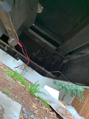
How to Wire a Backup Camera in a Skoolie
I plugged in the backup camera wire and ran it back along the top edge of the windshield, parallel with the power cable, and then ran it with some of the bus wiring towards the rear of the bus. There's a void in the wall, above the windows, that fits the wire harness, and simply ran it through there too.
But now I needed to use the extension cable. I ended up making this more complicated than it should've been.
The end of the backup camera cable (which plugs into the backup camera itself) has a stripped red and black wire used to automatically determine when the gear is in reverse (the "auto-backup-wires"). My plan was to remove the backup beeper and wire the cameras cables into its power source.
What I did was cut the main cable (the one that plugs into the dash cam--wire A plugs into the dash cam, wire B has the stripped red and black wire and plugs into the back up camera) and stripped the four wires inside. Then I sized up the extension cable, so that it would give me enough to make it to the rear of the bus, and cut both ends off there (wire C). Using the crimp toolkit, I then crimped wire A to wire C, and then the other end of wire C to wire B. Not only did I crimp the four wires together, but I also used heatshrink to make sure it was all secure.
In hindsight, I should've just plugged in the extension cable, crimped some extra 12v wire to the auto-backup-wires, and ran both the extension cable and the new auto-backup-wires to the back of the bus, and just stuffed the extra wiring behind a bulkhead. It would've saved me a ton of work, but whatever.
So now I have sufficient wiring to make it to the back of the bus.
How to Install a Backup Camera in a Skoolie
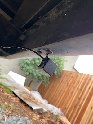
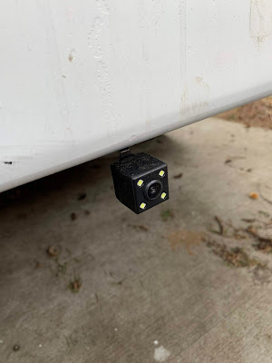
Bust out your drill and drill out a hole large enough for the backup camera plug through the floor (or wherever makes sense for you). Run the cable through this hole and make sure there's enough to reach wherever your installing the camera itself.
Then, position the camera where you want it (centerline under the bumper) and use an appropriate screw to install it. The provided screws were too small, so I used some extra self-tapping screws from old wiring I had removed earlier.
I then fed the wire above the strut toward the previously drilled hole, plugged it in, and turned on the accessories to verify it was powered up.
Now, for the auto-backup-wires, I found the buzzer, which was right behind the bumper, and removed it but left the wiring intact. I then attached the red auto-backup-wire to the power source, and the black one to the ground (which was simply bolted on to the bus's frame).
Next, I put the bus in reverse and verified that it knew I was in reverse.
The last step was to clean up the wiring a little. Using the wire clamps, I secured all loose wires to the bus so they wouldn't hang down and rattle loose. The main locations were under the rear bumper for the backup camera and at the top edge of the windshield. Everywhere else, the wires were well secured behind panels or in the wiring void above the windows, or stuffed behind an empty bulkhead.
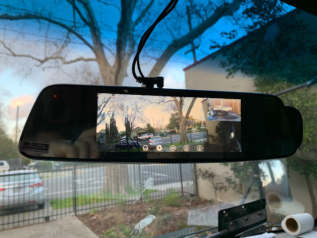
And voila! Now I have a dash cam that records about 2 weeks of video, both front and back, and a backup camera that automatically goes full screen when I'm in reverse.
|
|
|
|
|
03-27-2019, 12:25 PM
|
#36
|
|
Bus Nut
Join Date: Apr 2018
Posts: 421
|
Quote:
Originally Posted by Epomethius
Thank you for the pictures of the water tank support. How are you keeping the bolt heads holding the slotted angle metal off of the tank? What about abrasion?
|
Well you were kinda right after all. I just installed the grey and water tanks, and filled them both up to capacity to verify they would hold at full load. They do, but the sides expand out a LOT. The grey tank is fine, since there's less hardware on the left side, but the fresh water tank was pushing against these two thin flanges on the outer frame. I had trimmed them but apparently not enough, and they were digging in to the tanks. They would be fine for a few months of driving, but definitely would cut through after a few years of abrasion.
So I took the extra sheet metal from the interior wall demolition and made some protective pads and inserted them inside the frame. They're too big to slide out without bending the metal, so they should stay... I'll give it a few test runs and that should do the trick!

|
|
|
|
|
04-22-2019, 02:18 PM
|
#37
|
|
Bus Nut
Join Date: Apr 2018
Posts: 421
|
Frames for the Water Tanks
Here's how I did the frames for the water tanks:
Where to Mount a Skoolie Water Tank
This assumes it won't be inside the cabin, and will be hanging underneath the bus. Simpler is better, but this still requires careful planning on where and how to mount the tank--because this will dictate the shape of the water tank's frame. A few considerations:
- Sloshing. If you slam on the brakes with a half tank, there needs to be a way to absorb the force of the water crashing forward. This could be as simple as bolting the forward and aft edges of the water frame to the bus frame, such that it can't move forward and backward. In my case, the tank fit perfectly between the rear shocks (which takes care of aft movement) and the frame that supports the bus stairs in the front (which takes care of forward movement).
- Weight. Water weighs approximately 8 pounds per gallon. A forty gallon tank, at capacity, would weigh 320 pounds with just the water--not including the frame, tank, and hardware (those carriage bolts add up). A good safety margin is to multiply a fully loaded tank by 30% to get the max weight capability, so for that 40 gallon tank, we should plan on the whole thing weighing 416 pounds.
- Distribution. Don't just bolt the tank to the sheet metal floor. It may hold up initially, but after six months of wear and tear, the metal will easily fail. Don't risk dropping a tank while driving. The best way to mount it is to use the lateral spars of the bus frame, as those are designed to support a ton of weight. The more, the better. This may mean your tank frame has to extend beyond the tank dimensions to reach a spar.
- More distribution. The closer the water is to the center of the bus, the better the handling. Or, as in my case, the axles have different gross weights, so I wanted my water to be closer to the axle that can support more weight. Not just forward and aft, but lateral too. Unfortunately, because of the limited space underneath, the fresh water tank is pretty hard out to the right side, and the greywater tank is hard to the left. The lateral imbalance is not ideal, but it isn't as big of an issue as the forward and aft.
- Installation. Make sure it's possible to install both the tank and the frame. It sounds silly, but for my tanks, I had to install the frame first, and then the tank--but then I realized that I had no way of installing the tank into the frame while attached to the bus, as it sat too low. I could either jack the bus up, or remove part of the frame to slide the tank in, then reaassemble the frame--in any case, make sure it's possible to tighten all the nuts and bolts with the tank installed.
Now that you know where to mount your tank, and you have your tank from the previous post, we can design the frame. It needs to surround the tank, and fit in the space available.
How to Design a Water Tank Frame
At a minimum, all the corners and edges need to be supported by the angle steel. Those are the weak points and will be the first to fail if not protected. Second, the sides of the tank will expand when full of water--so while it may not come into contact with anything while dry, it may rub the bus frame when full. Someone much smarter than me said that a polypropylene tank is just to hold the water in--it needs support on all sides.
So at a minimum, I knew I needed all the corners and edges covered with angle steel, and a bottom to support the tank. What about the sides? I decided to leave them bare for two reasons: one, there were no sharp edges that would come into contact with the tank after it expanded (this proved false later on). Two, I was lazy, which is not ideal when designing a 400 pound tank hanging from the bottom of my DIY bus. As you can see, I did this the wrong way. If I had to go back and do it again, which I may do eventually, I'd take the extra sheet metal I ripped off the walls and use that to line all the edges, perhaps excluding the top, for protection from projectiles, from sunlight feeding algae, and from abrasion.
The last thing was how to mount it to the frame (which will be covered in a later post). Fortunately, a thick lateral spar ran across the exact center of where I wanted to hang my tank. This spar would support the bulk of the weight, although it would only be in the middle of the tank. The fore and aft edges of the frame would still be supported, only it wouldn't be held up by one of the spars (again, see the later post for more details).
The point is, this meant that all I had to do was create a box that contained the water tank. How to Build a Water Tank Frame
Measure thrice, cut once. I burned through multiple angle steel rods because I got the measurement wrong by an inch. And since I used the slots, this meant I had to scrap the whole piece and start fresh. Seriously, measure three times, and make sure each piece is as long as it's corresponding piece on the opposite side.
Then I slid the carriage bolt through two of the slots, such that the square of the head fit into the slot to lock it in place. Then I put a washer on (to distribute the pressure), a locking nut (to hold the thing in place, so that vibrations from the road wouldn't shake them loose), following by a regular hex nut tightened with a wrench until the locking washer was flattening.
Here are a few photos:

The above shows how I secured the different sides. Notice the top slot, where the two top angles overlap. This is where I planned to install the long carriage bolts (upside down) to mount the frame to the bus. Also note how it doesn't exactly line up--I had to use a drill bit to size the hole better to support the carriage bolt.
The plan was to install the frame to the bus, then slide the tank up into the frame, and install the plywood bottom. But this meant some of the bulkhead fittings wouldn't fit, so I had to cut away a portion of the angle steel.
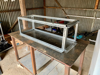
The finished frame. Note how the bottom angle faces out instead of in. This is because I had to install the frame to the bus, which meant the tank couldn't be in there (otherwise how would I install the long carriage bolts as mentioned above?), and then slide the tank up into the frame, and then bolt the plywood bottom to the outer flanges of the angle.
In hindsight, I could've designed it even better by making the vertical angle corners just a little bit longer, just long enough to support the plywood floor too--and then to install it, I'd just have to slide the tank up into the frame, and then hold the plywood in place, and then install the four bottom angle pieces with the flange facing inward, to hold up the whole thing. This would've been a lot more difficult, but also a lot stronger. The general theme for this project is that I should've spent the time to work a little harder to get a better finished product.
Speaking of which, this is the finished product.


A quick note about the bottom. It would be held up by the same carriage bolts, spaced a few slots apart to make sure it's secure. I predrilled these holes to make sure everything would go as smoothly as possible once the frame was installed on the bus. As you can expect, it didn't.
Common Gotchas
- Don't neglect the weight of the water. Putting 400 pounds over the rear bumper isn't such a good idea, nor is it to hang 400 pounds from just the sheet metal floor.
- Visualize how to install them as much as possible, because the design may not be compatible with how to install the frame/tank.
- Don't be lazy--do it right the first time. I should've put a sheet metal shield up around all the sides, and I should've installed the bottom with the flanges inward.
|
|
|
|
|
04-22-2019, 03:21 PM
|
#38
|
|
Bus Nut
Join Date: Apr 2018
Posts: 421
|
And finally how I installed the Water Tanks
How to Install Water Tanks on a Skoolie
I've got the tanks. I've got the frames. I know where and how to install them. It is imperative to do a "mock install" first to make sure everything fits, because guess what--they didn't.
They looked like they did, but I couldn't get them in place because of the rear suspension and the frame for the stairs. So I had to cut a divet in one of the angle steels so that it sort of wrapped around the suspension, and I actually had to cut away a small portion of the flange of the stair frame. Then I realized there were two flanges on the exterior wall (not structural) that would rub against the tank, so I cut away a portion of those too. This was an awfully irritating day.
I started with the grey water tank because I figured that would probably never be full, so it would be safer to "learn" how to install the tanks with that one in case I screwed up.
 Prepping the floor
I put the frame "in place" on the ground, then slid on my back underneath the frame and lifted it in place. Then, with goggles on and using a long bit, I drilled a hole next to the lateral spar (see my previous post for more info on that) that would be supported the frame. I drilled all four of those holes through the sheet metal floor. They were only approximate, as the spar is two inches thick, and I couldn't get the drill bit straight up and down.
Prepping the floor
I put the frame "in place" on the ground, then slid on my back underneath the frame and lifted it in place. Then, with goggles on and using a long bit, I drilled a hole next to the lateral spar (see my previous post for more info on that) that would be supported the frame. I drilled all four of those holes through the sheet metal floor. They were only approximate, as the spar is two inches thick, and I couldn't get the drill bit straight up and down.
Once all four holes were drilled, and brought the frame up into the bus and places it upside down such that the slots in the angle steel matched up with the four holes I just drilled. To hold it in place, I put carriage bolts in and then started drilling the rest of the holes in the floor in their corresponding slots.
All in all, I have 16 carriage bolts holding up the frame. Three at each corner, and four in the middle along the spar. At a maximum weight of 416 pounds (including g-forces at full load), that's 26 pounds per carriage bolt. With a 5/16" diameter carriage bolt that has a tensile strength of 100,000 to 125,000 psi, I think we're safe.
Next, I essentially repeated a similar process for the plywood, which I cut to shape (basically identical to the bottom board of the tank frame). So now I had all the holes cut into the sheet metal floor, and into the plywood that would go on top of the floor. It goes without saying to double check they all line up.
It's important to note that this is a very imprecise method. The holes will not be perfectly vertical, and as such the bolts will lean once they're installed. This is why I wanted such a high safety margin, using an excessive amount of bolts and the plywood backing and the spar.
This would be a good time to cut holes in the floor for the drain into the greywater tank, and the fill line for the fresh water tank. Once the tanks are installed, you don't want to be taking them back out again.
Okay, so now it becomes a two person job. I had my partner lay on her back and hold the frame up into place underneath the bus, while I was upstairs in the cabin. She took the long carriage bolts, threw a washer on, and then inserted them into the premarked slots that we used earlier. They passed through the angle steel, then the sheet metal floor, and then the plywood backing. It wasn't exactly easy, or pretty, but it worked.
Once the bolt was through, I put a washer down, a locking washer, and then a hex nut and tightened until it was "mostly" through. This meant the carriage bolt was sticking up like 3-4" inches off the floor. It's important NOT to tighten all the way because we have to wait for a full tank to do that.
We repeated this process for all sixteen bolts, and now had the frame loosely in place.
Next, we slid the tank into place, followed by the plywood bottom. While she held this up, I started bolting the plywood to the angle steel. This was a long and tedious process, as there were on the order of dozens of bolts to get through the wood. Same process here, with two washers, a locking washer, and a hex nut.
And ta-da, we now had our grey water tank "in place" but not tightened.
Back up top, with the hole already cut in the floor for the future sink drain into the grey tank, I started filling it up with a hose. This was a good opportunity to hold my breath because up to this point, I hadn't tested any of the bulkhead fittings to make sure they didn't leak, and to make sure it held up in place.
The good news is that it did.
With a full forty gallons of water in the tank, I started tightening the carriage bolts. How much to tighten them? There's no real good answer to that, unless you're in a lab with sensitive instruments. I just kind of eyeballed it to make sure the whole tank was level. I tightened it until the top angle steel of the frame was tight against the lateral spar, but the corners had no such metric. So again, I tightened them until the amount of carriage bolt that was above the floor was approximately the same as the four around the lateral spar. I also gave the tank some kicks and shoves, which simply shook the entire bus, so I decided that was sufficient.
Then I drained the tank and repeated the process for the fresh water tank. This took a few days overall.
Now that I had both tanks installed and secure, it was time to put the fill line in. I cut a hole in the outer wall of the bus in a place that wouldn't interfere with the future interior furniture, and in a position where it would gravity feed into the tank, and installed the fill valve. I used the foam filler to make sure no rainwater would leak behind the fitting, and to fill in the gaps on the inside.
Next, I installed the hose fitting to the fill port on the fresh tank, cut the fill and vent hoses to length, and installed them using the hose clamps.
Now they were fully installed, but I still wanted to ops test to make sure they were good. So I filled up the fresh tank and drove it on an hour long trip to make sure it held in place, even at full load and with the vibrations of the road.
And it worked just fine! There were a few leaks with the drain fittings, which I fixed using teflon tape, but now I have a two forty gallon tanks installed and secured!
Final note: There were two hot spots for the fresh tank that I missed when installing them, so I just inserted some sheet metal to protect the tank from abrasion against the two rogue flanges.
Common Gotchas
- Don't over tighten the long carriage bolts. This could bend the angle steel, which would just introduce another headache later on.
- The tanks are not level. I thought my driveway was, and did my best to eyeball it up, but in the end I prefered to have secure tanks that don't move instead of level tanks--although this means that I can't drain all the water in the fresh tank, as the drain is at the higher end.
- Take your time--this is a critical job because the last thing you'd want is for a large tank falling off under the bus while underway.
|
|
|
|
|
04-26-2019, 08:33 PM
|
#39
|
|
Almost There
Join Date: Dec 2015
Location: Rochester, NY
Posts: 77
Year: 2005
Coachwork: Blue Bird
Chassis: Ford E-450
|
Sweet looking build! Where did you get those 3/4" drains and what valve are you using for the drain?
|
|
|
|
|
04-27-2019, 10:28 AM
|
#40
|
|
Bus Nut
Join Date: Apr 2018
Posts: 421
|
Thanks, I try to get as much as possible from Amazon (my blog post has links to everything, but full disclosure: they're affiliate links). Here's a non-affiliate link to the drain mast:
https://www.amazon.com/gp/product/B0764NBD7L/
It's handy because it comes with the bulkhead fitting AND the ball valve (and it actually comes with an ADDITIONAL bulkhead fitting too).
Shameless plug for the blog post: https://theargobus.blogspot.com/2019...ater-tank.html
The only thing I wish I would've done differently is make the input to the grey water tank (from the sink drain and shower) 1.5" to standardize it with the hepvo traps. As it stands it's a two inch hole into the tank, and now I have to buy adapters to fit 1.5" anyway, sooooooo yeah the more you know.
|
|
|
|
|
|
 Posting Rules
|
You may not post new threads
You may not post replies
You may not post attachments
You may not edit your posts
HTML code is Off
|
|
|
|
 » Recent Threads
 |
|
|
|
|
|
|
|
|
|
|
|
|
|
|
|
|
|
|
|
|
|
|
|
|
|
|
|
|
|
|
|
|
|
|
|
|
|


 Linear Mode

