The kits are certainly the way to go. A small integrated circuit can easily handle timer duties. However, I figured I should just post a diagram of a completely analog intermittent wiper setup I built a few years ago for an S-10 I owned out of parts I had floating around the garage. It was noisy and inefficient, but I'll be damned if it didn't work great.
Components:
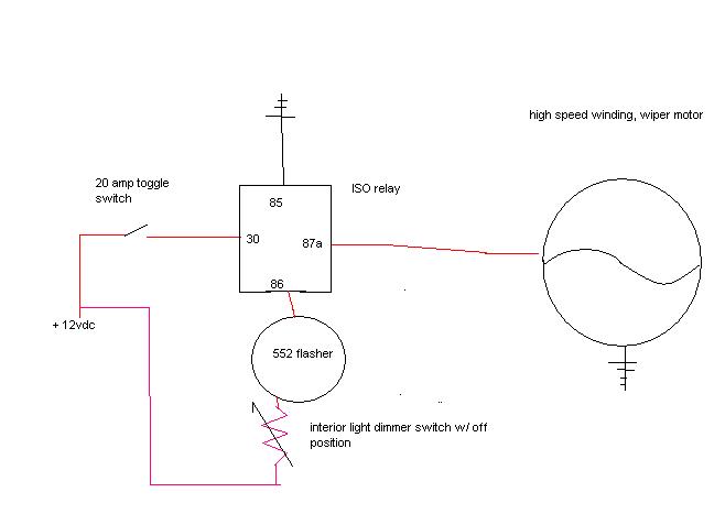
In the diagram you will see just a very few components. The actually power supply to the wipers was a fairly sizable fused wire going to the high speed winding of the motor. Applying power here would turn the wipers on. I put a toggle switch inline to "arm" the system. Without it my intermittent wipers would leave the wipers on the high speed setting all the time, regardless of where the factory wiper switch was positioned. There is also an ISO relay. I used one for the blower on an OBS Chevy truck as you can find 3 of them with socket conveniently located behind the glovebox of any of these trucks with solid state heater controls.
On the control side of things I used a variably resistive switch on a fused wire. My switch happened to be the interior light dimmer from a 1984 Toyota truck though I suppose anything could work provided it will allow you to vary the output voltage from 0-12 volts. The switch is then wired to a common $.50 552 flasher unit (this one came out of the same Chevy as the relay), and then to the control side of the relay.
Theory of operation:
All wiper motors have a mechanical park switch. The function of the switch is to return the wipers to the fully retracted position even if you interrupt power via the wiper switch with them up. It is this function that I capitalized on.
The intermittent power supply to the wipers is wired through the normally closed side of the relay. This means that as long as power is not supplied to the relay current is allowed to flow and the wipers will operate on high speed (hence the arming toggle switch).
Old fashioned thermal flashers such as the 552 I used rely on a the heat generated from a resistive bimetallic strip internally to open the circuit. This is the actual clicking you hear. As current flows through the circuit (such as your turn signals), the strip heats up. At a certain point the contacts open and the lights turn off. When the strip cools enough the contacts touch again and lights (or other circuit components) turn back on. At 12 volts with a normal load of lights in a car this happens pretty quickly over and over again.
But...what happens when you plug the trailer lights in? The current demand in the circuit decreases (series circuits, remember) because the resistance increases and the lights flash slower. What about when a bulb burns out? The total circuit resistance decreases as one of the parallel series legs of the circuit is open and the light flashes much more quickly.
I aimed to replicate this with the dimmer switch. By rotating it I could control how much load there was and how often the flasher would pulsate. When the resistance was high the current was low and the flasher would break the contacts very infrequently (but took the same amount of time to cool and reset regardless). As long as the circuit was closed and the current was flowing through the breaker the relay would be held "on" which in fact interrupted power to the normally closed 87a contact and the wipers would be off. When the flasher broke the control circuit the relay would turn "off" which would in fact turn the wipers on. Even though the flasher quickly applied power to the circuit again, thus turning the relay "on" and the wipers "off" the mechanical park switch integral to the wiper motor would cycle them fully.
Sorry for the poorly drawn diagram. MSPaint doesn't lend itself well to schematics.


 Linear Mode


