 |
 01-01-2014, 08:05 PM
|
#1
|
|
Bus Nut
Join Date: Jul 2012
Location: Olympia, Washington
Posts: 557
Year: 87
Coachwork: Wayne
Chassis: International s1700
Engine: 6.9 internatiional
Rated Cap: 65
|
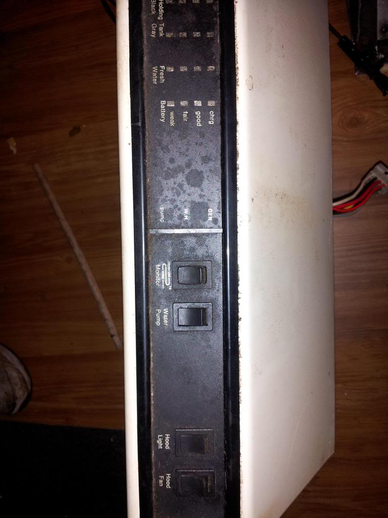
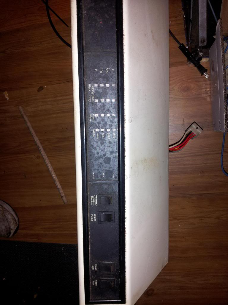
Range hood wiring diagram
Hi folks,
for the life of me i cant find the wiring diagram for a Range hood. it has 7 wires on the harness, and im sure some of the wires are for tank sensors etc. if you guys have any ideas what each of these wires do i would be grateful.

thanks
Eric
|

|

|
|
01-03-2014, 06:25 PM
|
#2
|
|
Bus Crazy
Join Date: Jan 2008
Location: Adirondack Mountains NY
Posts: 1,101
|
Re: Range hood wiring diagram
Unless someone has the same exact unit as you, a photo of the connector probably won't help. Time for some detective work. If you could advise whether the fan and light are 12 VDC or 120 VAC, that would be a start. To really get an answer, you need to either measure the wires with a meter, or open up the hood and get a photo of where the colored wires attach to the panel or sub-assemblies.
I will assume for a minute that you have 12 VDC fan and light. I expect there are the following wires:
+12 VDC battery hot for everything, probably including the battery meter
- 12 VDC ground for at least the fan, light and gauges
Switched +12 VDC out to run the water pump
input from sensor for the water tank
input from sensor for the grey tank
input from sensor for the black tank
That is six out of seven. I expect the seventh might be a switched ground for the water pump. It could also be reference for the tank sensors instead of using the vehicle chassis or batteries. Or it could be an independent battery wire for the voltmeter, to get a more honest reading direct from the battery, without the "IR" voltage drop due to current being drawn on a wire shared with the light(s), fan, and water pump.
You can't trust the colors, because automotive practice uses red for positive and black for negative, while RVs often use trailer colors which match house wiring - black for positive and white for negative. The battery positive and negative could follow either system, or its own.
The thickness of the wires is a clue - if there are larger and smaller wires, the high current wires that power everything would be larger, and the low current wires that sample the three tanks would be smaller.
If I were a betting man (which I am not), I would guess that the three wires in the foreground look smaller, and might be the tank meters. I would pick the red and black as battery wires, and the white and yellow as switched pump wires.
But you should be able to figure this out for yourself.
If you open the case for inspection, the ground wire should go directly to the fan, light socket(s), and the indicator board. It may also go to the pump switch if the switch has 4 wires.
The battery wire should go the to fan switch, the light switch, and the pump switch. It should also power the indicator board, either direct, or through the monitor switch first, so the board is only live when the switch is on. I would not be surprised if the switch is spring-loaded, so that you have to hold it to check the tank levels.
The three tank indicator wires should go directly to the indicator board.
Any switched hot wire out to the water pump should go ONLY to the pump switch.
The seventh wire may be a switched pump ground in addition to a switched hot, so an RV manufacturer could wire the pump multiple ways. If so, there will be 4 wires on the pump switch. A pump could be wired always grounded with a switched hot, always hot with a switched ground, and with both hot and ground switched for extra safety.
********
If you know how to use an ohmmeter, you should be able to get the fan, light, and pump figured out without opening up the hood, as long as you can get the light bulbs out of their sockets.
1. remove the light bulbs, so no false ohmmeter readings pass through the filaments
2. turn all the switches off, especially the fan for the same reason
3. measure from the threads or side of one of the light sockets, and find the wire that reads zero ohms, or pretty close to it. This would be the ground.
- It is possible that incandescent bulbs would be in series for lower light but almost unlimited life. If there is more that one light socket, and the first one has no ground, try the other one.
4. turn on only the light switch. measure from the button in the bottom of a light socket to find zero ohms to another wire. When you find it, flip the switch on and off a few times to confirm it is correct. This would be the battery wire.
5. once you find the battery wire, turn the light switch off and the water pump switch on, and find another wire that connects to the battery wire with nearly zero ohms. When you find it, flip the switch on and off a few times to confirm it is correct. This would be the water pump hot wire.
6. repeat step 5 between the ground and the unknown wires, to see if there is a switched pump ground
Unless there is a lot of stray paths through the battery condition meter on the circuit board, this method should have the basic 3 or 4 connections covered to use the fan, light(s), and water pump control.
__________________
Someone said "Making good decisions comes from experience, experience comes from bad decisions." I say there are three kinds of people: those who learn from their mistakes, those who learn from the mistakes of others, and those who never learn.
|
|
|
|
|
01-04-2014, 11:12 AM
|
#3
|
|
Bus Nut
Join Date: Jul 2012
Location: Olympia, Washington
Posts: 557
Year: 87
Coachwork: Wayne
Chassis: International s1700
Engine: 6.9 internatiional
Rated Cap: 65
|
Re: Range hood wiring diagram
Thanks Redbear, you gave me some great information here. I think i will get out my meter and ohm out some of the connections. you are correct about the wire size differences. i have taken a picture and separated the wires into their 3 different size groups the middle red and yellow are the largest, black and white to the left are the middle size and small red, brown and Grey are to the right in this picture:
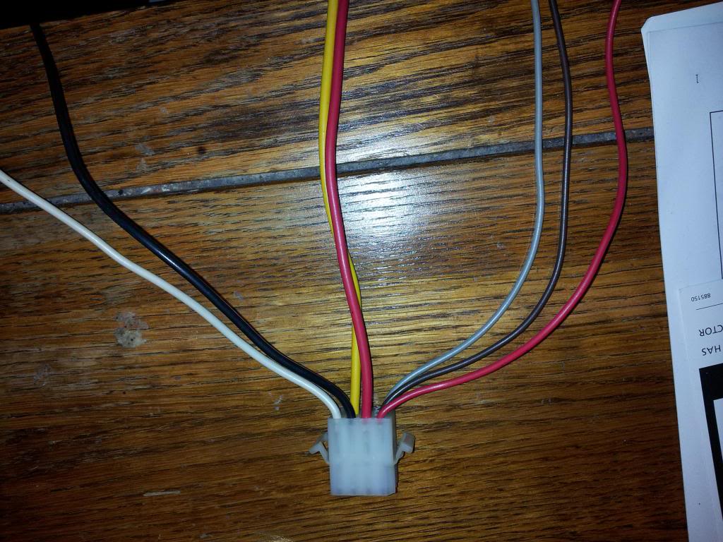
thanks
Eric
|
|
|
|
|
01-04-2014, 05:20 PM
|
#4
|
|
Bus Crazy
Join Date: Apr 2013
Location: Colorado
Posts: 2,359
Year: 1993
Coachwork: bluebird
Engine: 5.9 Cummins, Allison AT1545
Rated Cap: 2
|
Re: Range hood wiring diagram
i feel smarter for having read that 
|
|
|
|
|
01-05-2014, 09:02 AM
|
#5
|
|
Bus Crazy
Join Date: Nov 2010
Location: Andrews,Indiana
Posts: 2,436
Year: 1991
Coachwork: Bluebird
Chassis: AARE
Engine: 3116 Cat 250hp
Rated Cap: Just the two of us.
|
Re: Range hood wiring diagram
Is it not possible to simply open the panel and see where the wires go?
|
|
|
|
|
01-05-2014, 09:50 PM
|
#6
|
|
Bus Nut
Join Date: Jul 2012
Location: Olympia, Washington
Posts: 557
Year: 87
Coachwork: Wayne
Chassis: International s1700
Engine: 6.9 internatiional
Rated Cap: 65
|
Re: Range hood wiring diagram
Quote:
|
Originally Posted by somewhereinusa
Is it not possible to simply open the panel and see where the wires go?
|
i want to, but i am afraid of breaking the panel, as i cant see how it is attached, thats why i was looking for someone who might have this hood. im going to try ohm-ing it out first, last resort will be to pry the plastic panel off.
|
|
|
|
|
01-18-2014, 08:18 PM
|
#7
|
|
Bus Nut
Join Date: Jul 2012
Location: Olympia, Washington
Posts: 557
Year: 87
Coachwork: Wayne
Chassis: International s1700
Engine: 6.9 internatiional
Rated Cap: 65
|
Re: Range hood wiring diagram
i removed the front panel and i am examining it now. the connector on the left is for the fan and light so i know i can get those 2 working.


|
|
|
|
|
01-19-2014, 10:31 PM
|
#8
|
|
Bus Crazy
Join Date: Jan 2008
Location: Adirondack Mountains NY
Posts: 1,101
|
Re: Range hood wiring diagram
My analysis:
The external black goes to the fan switch, the light switch and to the monitor switch - it is the hot.
The internal black goes from the monitor switch to the circuit board - it is the switched hot for the level gauges.
All the whites are spliced together - the fan, the light, and the circuit board - they are the grounds.
The red goes only to the water pump switch - it is a hot from a dedicated water pump fuse, so it can be separate from the range hood fuse.
The external yellow goes out to provide power the water pump.
The internal yellow provides power to the water the pump power on indicator on the monitor board.
The three small external wires are for the three tanks as previously guessed.
The empty pins in the middle of the circuit board connector are for the optional water heater and generator indicators.
It is a nifty way to have all your basic indicators at eye level. I think it's kind of cool.
__________________
Someone said "Making good decisions comes from experience, experience comes from bad decisions." I say there are three kinds of people: those who learn from their mistakes, those who learn from the mistakes of others, and those who never learn.
|
|
|
|
|
01-26-2014, 01:00 AM
|
#9
|
|
Bus Nut
Join Date: Jul 2012
Location: Olympia, Washington
Posts: 557
Year: 87
Coachwork: Wayne
Chassis: International s1700
Engine: 6.9 internatiional
Rated Cap: 65
|
Re: Range hood wiring diagram
Quote:
|
Originally Posted by Redbear
My analysis:
The external black goes to the fan switch, the light switch and to the monitor switch - it is the hot.
The internal black goes from the monitor switch to the circuit board - it is the switched hot for the level gauges.
All the whites are spliced together - the fan, the light, and the circuit board - they are the grounds.
The red goes only to the water pump switch - it is a hot from a dedicated water pump fuse, so it can be separate from the range hood fuse.
The external yellow goes out to provide power the water pump.
The internal yellow provides power to the water the pump power on indicator on the monitor board.
The three small external wires are for the three tanks as previously guessed.
The empty pins in the middle of the circuit board connector are for the optional water heater and generator indicators.
It is a nifty way to have all your basic indicators at eye level. I think it's kind of cool.
|
i checked this out with 12Vdc and a meter, and i believe you are correct. thanks for figuring this out Redbear.
|
|
|
|
|
01-07-2022, 11:00 AM
|
#10
|
|
New Member
Join Date: Jan 2022
Posts: 3
|
Fuses for panel
Redbear thank you for the information you have provided on this monitor panel. I have no power on my panel I believe it is the fuse, but have not been able to locate where it is. In your reply you mentioned a dedicated fuse for the water pump and a dedicated fuse for the panel. Where are these located?
|
|
|
|
|
01-07-2022, 01:22 PM
|
#11
|
|
Bus Geek
Join Date: Sep 2017
Location: Swansboro,NC
Posts: 2,988
Year: 86
Coachwork: Thomas
Chassis: Ford B700
Engine: 8.2
Rated Cap: 60 bodies
|
Quote:
Originally Posted by Tnine11

Redbear thank you for the information you have provided on this monitor panel. I have no power on my panel I believe it is the fuse, but have not been able to locate where it is. In your reply you mentioned a dedicated fuse for the water pump and a dedicated fuse for the panel. Where are these located?
|
tnine
i havent seen either of these posters on here in years?
it might be easier/quicker for you to start a new post with your specific make model and problem.
with your make model we might be able to help figure it out.
|
|
|
|
|
01-08-2022, 08:54 AM
|
#12
|
|
New Member
Join Date: Jan 2022
Posts: 3
|
Thank you, I'll try that
|
|
|
|
|
| Thread Tools |
|
|
| Display Modes |
 Linear Mode Linear Mode
|
 Posting Rules
|
You may not post new threads
You may not post replies
You may not post attachments
You may not edit your posts
HTML code is Off
|
|
|
|
 » Recent Threads
 |
|
|
|
|
|
|
|
|
|
|
|
|
|
|
|
|
|
|
|
|
|
|
|
|
|
|
|
|
|
|
|
|
|
|
|
|
|


