 |
|
 04-17-2020, 07:51 PM
|
#121
|
|
Bus Nut
Join Date: Apr 2018
Posts: 421
|
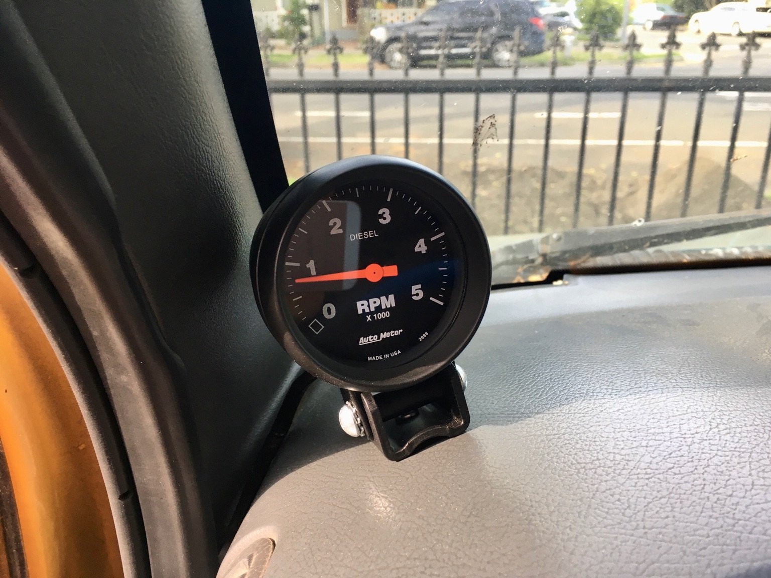
Just got an aftermarket engine tachometer installed. I bought this one here, brought it in to the shop, and they installed it for me as I couldn't figure out how to reach the alternator to do it myself. It seems to work just fine for RPMs above 1000 and cost $337.50 to install and I freaking love it!
|

|

|
|
04-17-2020, 07:54 PM
|
#122
|
|
Bus Nut
Join Date: Jan 2015
Location: Brazoria County, Texas
Posts: 819
Year: 1997
Coachwork: Carpenter
Chassis: International
Engine: T444E
Rated Cap: 32 Passenger
|
Quote:
Originally Posted by TheArgobus

Just got an aftermarket engine tachometer installed. I bought this one here, brought it in to the shop, and they installed it for me as I couldn't figure out how to reach the alternator to do it myself. It seems to work just fine for RPMs above 1000 and cost $337.50 to install and I freaking love it!
|
Careful with that clutch. I can see it now ..... Wheelstands in the neighborhood!!!
|
|
|
|
|
04-17-2020, 10:05 PM
|
#124
|
|
Bus Nut
Join Date: May 2018
Location: Wamego Ks
Posts: 617
Year: 2007
Chassis: Collins
Engine: 6.6L LMM Duramax
|
Quote:
Originally Posted by TheArgobus
|
Haha!! Love it! Nothing like a wheelstander!!
|
|
|
|
|
04-19-2020, 12:54 PM
|
#125
|
|
Bus Nut
Join Date: Apr 2018
Posts: 421
|
How to Plan your Skoolie Electrical System
Finally got around to documenting my process. I really need to emphasize that I am not an electrical engineer, I don't use the correct terminology or electrical schematic symbols, and I don't think anyone should take electrical advice from me. There are folks on this forum who are way smarter than I am, and I'm sure they'll correct my errors. In any case, this is just a documentation of what I did--not the right way to do it, but just the way I did it.
How to Plan your Skoolie Electrical System
Note: this post only covers the battery bank, the charger, and a few other components. Solar, electrical panels, and other electrical items will be covered in future posts.
This will likely be the most complicated portion of the buildout. At least it was for me. There are so many steps in here and ways to screw up that it's impossible to get it perfect. I'm not an electrical engineer, and I definitely screwed my installation up, so don't listen to anything I have to say, unless it's on what not to do.
I also can only describe what I did with my unique situation, so I don't cover all the other potential electrical scenarios. I don't cover AGM batteries, or large AC systems, because I don't have either. But perhaps by seeing my method, you will get ideas on how to complete your own system or avoid making the same mistakes.
The general strategy is this: learn how electricity works, budget your electrical needs, decide on your battery type, primary charging system, and just how much you're willing to spend on this (warning: don't skimp on the electrical). Since all of these will be dependent on every specific bus and owner, I'm only going to cover what I did and my thought process through each step.
How Electricity Works (for Dummies)
If you already know, then just skip this section. This is based on my understanding of electricity, with respect to Argo. Keep in mind I am not an electrician or electrical engineer, so this is my dumbed down way I make sense of things. If you know more about this than I do--which is most likely the case given my limited understanding--then you will probably cringe at the whole thing.
There are two types of electricity, or current, for RVs/Skoolies/Boats/Airplanes/Argo: alternating current (AC) and direct current (DC). Both have their own advantages and disadvantages for various applications. AC is the standard household current generated at power plants and transmitted to your wall outlet. The current alternates back and forth many times per second--imagine that it's pushing current out, then pushing it back, then pushing it out, and back. In fact, in the US, this happens 60 times per second, or 60 hertz ( watch any slow motion video of an AC lightbulb, and you can see the bulb dim as the current switches directions). AC can reach higher voltages no problem, and experiences relatively little voltage drop/degradation over long distances, which is why it can travel hundreds of miles along power lines. We generally see AC as three wires: the hot/phase/line wire (represented with simply "L" or "HOT" and with the color black--it's also the smaller flat prong on an outlet) is where the current cycles back and forth; the neutral wire (represented with "N" and the color white--it's also the larger flat prong on an outlet) is what allows the current to cycle back and forth along the hot line; and lastly the Earth/ground wire (represented with the "E" or "G" or this symbol (⏚) as green, as the color green--it's also the bottom circular post on an outlet) is what protects you from shock due to unintentional shorts. The standard for the US is 120V at 60Hz.
DC, on the other hand, pushes current only in one direction: from the positive side to the negative side (although this doesn't necessarily mean electrons follow this direction, but that's not important here). Because DC pushes current along the entire wire, or circuit, it experiences much more voltage drop/degradation over long distances. Imagine an electron moving in a DC circuit--it has to travel the full distance along the entire wire. But an AC electron only moves a small distance before getting pushed back when the current alternates.
Here's a few generalizations about AC and DC:
- AC is easily generated by things that rotate, such as a turbine wheel that spins from steam or water, or a spinning belt attached to an engine
- DC is easily generated by chemical energy, such as the reaction of photons with silicon (solar panels) or the difference between two voltaic cells (also known as a battery)
- As with its generation, AC is used to power motors, such as a compressor on an air conditioner or refrigerator, or anything else that has a high power consumption
- DC is used to power computer circuits, LED lights, and anything else that requires a small amount of power to run
- One can convert AC into DC with a rectifier, and DC into AC with an inverter, but both result in inefficient power loss
What is voltage? Well, the simple way I view it is that voltage is the potential energy of an electrical circuit, or the electrical pressure behind whatever is pushing the current. It's not necessarily the force of the current, just the potential of the current. Amps, on the other hand, are a measurement of how much current is actually flowing through the circuit. The simple way I picture it is a bucket of water with a hole at the bottom: the more water in the bucket, the higher the pressure to push water out the hole. So if there's a higher amount of water (a higher amount of voltage), then it takes a lot less energy to push water out (a lot less amps to accomplish the same thing). These two are related and tied together, and thus it's handy to think of electricity in terms of watts, which is simply the voltage times amps.
Why use watts? Well, imagine a DC powered refrigerator that can accept both 12 and 24 volts. If it receives a 24 volt power source, it requires half the amps as it would if it received a 12 volt power source (if you double the voltage, or the electrical pressure, then you only need half as many electrons flowing to accomplish the job). If, for example, its power consumption is about 100 watts, the 24 volt source would only need to supply ~4 amps, and a 12 volt power source would need to provide ~8 amps.
Something else to consider with amps is that, since this is a measurement of how much current is actually flowing through the wire, it will generate heat in this wire. More amps means more electrons are flowing, which means more heat is being generated in the circuit. If your wires are too small, they'll start to get quite hot--so it needs to be sized properly. More amps means a thicker wire to handle the increase in energy. Thicker wires are generally more expensive.
Side note: wire thickness is measured in wire gauge, with a higher gauge meaning a smaller thickness.
Okay, so we've got voltage (potential energy), amps (actual amount of current flowing through the circuit), and their relationship expressed as watts (volts times amps). Typically, things that don't require a whole lot of power (like LED lights, small water pumps, computer circuits) use DC, and as such these are usually powered by batteries. Higher draw items, such as air conditioners, full size refrigerators, and electric heaters are powered by AC, because not only are they powering a compressor, they require more amps to run. If the voltage is higher, then they can use less amps, which doesn't only cost less, it's safer.
Since Skoolies spend the majority of their time with the engines off, the primary power source for Skoolie living is DC from the battery bank. It's quite common to see this DC battery bank also powering an inverter, which then provides 120V AC power, and for those with the space, a generator that provides steady AC power.
That is a super basic, super generalized, not-totally-accurate representation of electricity for Skoolies.
How to Budget a Skoolie's Electrical Needs
I tallied up how many things I wanted to use electricity on my Skoolie, and planned on a worst-case scenario: powering everything at the same time. Unrealistic, but something good to plan for. So I found all the product manuals for the items I have, and counted up their power consumption in watts to plan out my electrics.
DC components:
- LED ceiling lights at 9W x 5: 45 watts
- LED exterior illumination lights at 2.7W x 5: 13.5 watts
- Exterior flood lights at 51W x 4: 204 watts
- Water pump at 92 watts
- Refrigerator at 68 watts
- Diesel heater at unknown wattage, but it probably isn't more than 20 watts
- Cell phone charger at 18 watts
- Additionally, I have two vent fans for my electrical compartment and for my refrigerator that run at 4.8W x 4: 19 watts
(For links to the actual items I used, please visit my build blog here--it contains Amazon affiliate links so I have to remove the hyperlinks when I post here).
That's a grand total of about 500 watts for my DC components.
What about my AC power?
I have an inverter/charger combo set up, and the only AC component that I see myself using is the almighty air conditioner. However, I am counting on a 30% loss of efficiency at the inverter, which is worse than it actually is, but like I said: I'm planning on worst case scenario.
1000 watts is 1000 watts no matter if it's coming from 24v or 120v. But if the AC power is coming from DC through an inverter, I need to count for that 30% inefficiency. The way I do this is take the end goal--in this case, an air conditioner than runs at 450 watts--and multiply its rated wattage by 1.30 to get 585 watts. This means that the inverter needs to get 585 watts of DC power to produce 450 watts of AC power. Since I'm trying to size my battery bank, I need to account for these AC power draws in terms of DC.
So I have to add that 585 to the 500 from before, and my worst case, everything running at max blast scenario, I need 1085 watts of battery power available.
This is completely unrealistic though. The water pump doesn't run continuously for an hour, and why the hell would I be running both my air conditioner and heater at the same time? And why would I have the flood, illumination, and interior lights on at once? And the fridge won't be running its compressor the whole time. A more realistic scenario is to think about electrical use over 24 hours.
- Ceiling lights will be on for two hours: 90 watts
- Exterior illumination lights will be one for two hours: 27 watts
- The water pump will run for twenty minutes per day: 31 watts
- When the refrigerator runs its compressor, it draws 68 watts. But since it doesn't run all the time, it's rated for, over the course of 24 hours, only 400 watts
- Sure, I'll charge my phone over the course of one hour: 18 watts
- Let's just say that the vent fans run for a total of two hours per day: 40 watts
- Air conditioning. Well, let's come back to this one later.
Realistically, I'd be pulling about 600 watts per day. Since I'm sure that's an underestimate, let's tack on 30% and round up to get 800 watts per day. From here on, I'm going to use this 800 watts as my planned daily electrical requirement. Remember, this is based on a realistic amount of use, plus 30%.
What about the air conditioner? I will revisit that later.
How to Size Your Skoolie Battery Bank
In my unprofessional opinion, a good method to come up with the right size bank is to take your realistic 24 hour requirement and multiply it by three days. So for me, I'd need 2400 watts of battery capacity to run, unrecharged, for three days. I think 2400 watts is a good goal.
However, I cheated.
A colleague of mine, who lives with his family on his 40 foot toy hauler, imported hundreds of 3.2V 30 amp hour lithium iron phosphate battery pouches from China. He had to go to customs in person to prove that he wasn't importing them for business, and he sold me 40 of these for a great deal. I couldn't say no.
So I have forty 3.2V, 30 amp hour LiFePo4 pouches. Or, expressed in terms of watts: 3,840 watts.
If I didn't buy them, I'd still go for LiFePo4 batteries, probably from Renogy, but that's only because I ended up getting their solar panels. That will be for another post.
The benefits of LiFePo4 are clear: they last much longer than the alternatives, they can be drained completely safely, and charge quickly too. However, the disadvantages are also clear: they are incredibly expensive, they require specific chargers, and it is really easy to completely brick your pack. For me, I countered these points by obtaining them for $17 a cell, my inverter/charger has a LiFePo4 option, and I also have a battery management system (that has been nothing but an absolute headache, but I finally got it working). These also require cell balancing, such that each cell doesn't deviate from the others too much, and I also picked up 8 balancers. As you can see, the main disadvantage of lithium is just how much you have to spend not just on the batteries, but also on the protective gear.
12 or 24 Volts?
The benefit of a 12 volt system is that it's the standard automotive voltage. Most vehicles and RVs run on 12 volts, and thus there's a wider selection of parts and accessories in 12 volts. You can also combine your house bank with the bus bank in creative ways, such as charging your house bank from the engine when it's running, and using your house bank to jump start your engine.
The benefit of a 24 volt system is that, as noted earlier, higher volts means less amps, which translates to smaller wires. Smaller wires cost less money, and you can fit more in a given conduit. There's less of a voltage drop over a given length of wire, which is particularly meaningful if you have a full size bus, and most solar panels operate in voltages in excess of 24V (meaning that, compared to a 12V bank, you'll have greater efficiency when charging off of solar).
My end goal, ultimately, is to run an air conditioner off solar panels without draining too much off my batteries. That means I have to maximize efficiency everywhere, and the choice was clear: I need a 24V bank.
How to Charge your Skoolie Batteries
There are a few ways to charge your batteries:
- Shore power (typically from those funny shaped 30 amp outlets at RV parks)
- Solar panels
- A gas/diesel/propane generator, sometimes able to run while the bus is in motion
- The engine's alternator or battery bank (commonly known as DC-DC chargers)
Argo spends the vast majority of her time in my driveway, meaning she'll be plugged in to shore power to keep the batteries topped off. Most of our planned destinations do not have shore power, however, so we had to decide on one of the other methods. Since I went with 24V, I ruled out the engine's 12V alternator, and I also don't have a whole lot of space or the desire for a gas powered generator. That left solar panels as the logical option.
Argo isn't very long, and we already have a sunroof in, so roof space is limited. However, after browsing a few different options, we found a suitable option: a 24V 300W solar panel, of which three would fit on the roof with a few inches to spare. That would be 900W of solar power if running at 100% efficiency, which is not likely at any point in time. If we instead say we're running at 60% efficiency, due to the angle of the sun with the flat roof, and any potential shade, that's still 600W of solar power pumping out every hour during the day (I think?). If we can get just 4 hours of that, not only does that greatly exceed our 24 hour energy use of 800 watts, but it would fully recharge the battery bank if they were completely depleted.
However, that's just the plan. Who knows if it'll work out that way (probably won't). For now, I'm just doing the shore power plug because I don't have the time to do everything at once.
So now I need to get a 24V LiFePo4 charger that can run from 120V shore power. At the recommendation from my friend, I went with AIMS Power and got their 2000W Inverter/Charger, with the bonus LCD Control Head. Some people recommend getting separate inverters and chargers, but since I have a small bus with few electrical needs, I see no problem in combining them into one unit.
Okay, so to recap so far:
- I need 800W daily
- I have forty 3.2V 30 amp-hour LiFoPo4 batteries
- My bank will be 24V
- I have a 2000W inverter/charger combo
- The bank will primarily be charged by shore power, with the option for solar in the future
Other Electrical Safety Gear
There are two other items that I needed to get to finish my battery bank. One, I want to be able to monitor the bank health, status, state of charge, and get a low voltage alarm. Two, I want to be safe.
For the first, I went with the Victron Energy Battery Monitor. This uses a shunt, which is essentially a device that measures voltage and current flowing through a specific circuit, and a display head that can be customized for your bank. For the second, I picked up a 100 amp ANL inline fuse that does exactly what you'd expect: if there's a short anywhere in the circuit after the fuse, the current will start to rise dramatically, and when that current exceeds 100 amps, it will break. 100 amps at 24 volts is 2400 watts, which is an enormous amount of current, and I don't see that ever happening, so I'm probably going to replace it with an 80 or 60 amp fuse.
We also have to protect everything else in the circuit, not just when these things are powered, but also when they're not powered and I'm working on the electrical system. This requires careful planning and usually involves a fuse or circuit breaker panel and master battery switches.
The general idea is this: the battery pack is its own beast, sitting by itself in a protective box, with a positive cathode and a negative anode. The very first thing the current, flowing from the positive cathode, encounters in the master inline fuse (this is the worst-case scenario safety device, as it will protect against any short after it in the circuit but not before it--thus it needs to be the very first thing on the positive side). This fuse then leads to two things: the inverter/charger (so it can charge whenever it's plugged in) and the master battery switch at the electrical control panel. This master battery switch then leads to the circuit breaker panel, which is essentially my on/off switches for all my electrical devices.
I have six circuit breakers: cabin lights, exterior lights, water pump, refrigerator, heater, and auxiliary electrical devices. If the master battery switch is off, then no current flows to the circuit breaker panel, but the batteries can still charge because the inverter/charger is connected back at the inline fuse.
If I turn the master battery switch on, then the circuit breaker panel gets power--if I turn, say, the interior light circuit breaker on, then the current flows out the circuit breaker and into the wire leading to the lights. If there's a short somewhere in the light wiring, then the current will dramatically increase, which will get the circuit breaker quite hot. Once it gets too hot, it will automatically flip and break the circuit (hence the name). Other electrical devices will still be able to get power, but now you know which circuit is damaged. Fuses will do essentially the same thing, but require a new fuse to be installed whereas circuit breakers can just be reset (obviously make sure you repair the shorted circuit first).
If everything is working in this scenario, then the current leaves the circuit breaker, travels through the positive wire to the light fixture, emits light in the LED, then returns through the negative wire back to the electrical control panel. All the negative return wires are connected to a common bus, which is then wired back to the battery bank. It's important to note that all wires going to and from the battery bank, prior to the circuit breaker panel and after the negative common bus, are sized appropriately (6 AWG in my case).
The current leaves this negative common bus and returns to the battery compartment (which I call the E-Bay as a sort of inside joke), and is attached to the shunt. This shunt measures the current flowing and can monitor the battery pack health and state of charge. This shunt then runs to the negative anode of the battery pack, thus completing the journey. (It's worth noting that, between the negative anode of the battery pack and the physical battery itself, I have inserted another master battery switch which allows me to turn the actual battery pack on and off).
Pretty simple, right? Here's a shitty picture of what I just described:
Note: I have no idea if the symbols are correct, I just used the free schematic maker here.
Common Gotchas
- Unrealistic energy budgets--once you start adding big AC appliances, such as full size refrigerators and washing machines, you really have to start considering a generator--unless you have a massive battery bank with a massive solar farm
- Getting everything at once--you don't need to build everything at once, as that can get pretty expensive, and it also prevents you from trying things out as you go, which gives you a better idea of what you really want/need
- You get what you pay for--electricity is one of those areas where I will never buy cheap tools or gear. For example, I ponied up for a pure sine wave inverter instead of a partial for cleaner AC, I absolutely required an inline fuse first thing out of the battery pack in case there's a short somewhere in my shoddy wiring (everything is protected by a fuse of some sort, or the circuit breaker box), and I didn't skimp on the wiring--I used online wiring calculators like this one and absolutely never got a wire too small. This meant I had to purchase special crimping tools to adequately splice 6 AWG wire, and everything starts to add up fast. But I'm okay with this added expense because of how easily a bad electrical component can destroy the entire bus.
|
|
|
|
|
04-19-2020, 04:11 PM
|
#126
|
|
Bus Nut
Join Date: Dec 2018
Location: Mt Vernon, WA
Posts: 523
Year: 1996
Coachwork: Bluebird, Collins
Chassis: G30 Bluebird Microbird, E350 Shuttle Bus
Engine: 1995 Chevrolet 350, 1992 Ford 460
|
Thanks, lots to digest in that description. Give yourself credit. You did a decent job thinking that system through. Let us know how that bms works for you. Im learning about them. What bms did you go with?
How did you decide where to put everything? I’m thinking about installing my energy system in my 4 window Microbird now. I’m thinking of placing everything at the very front in that awkward spot where the fire extinguisher is sometimes placed in front of the stairs. Then I can work on it by the door and see if it’s working good whenever I go in or out of the bus. And I like to bring some of the weight forward. I’ll see if the batteries will fit next to the engine doghouse today. And if the inverter/charger will fit. It will be tight.
I bought a DC-DC Charger. I’m hoping I can use the existing bus power cable for the school bus lights, beepers, stop sign, etc to conduct power from the starting battery to the charger. I’ll go look at it today and see what size cable they used. All I need is 6 guage for my 50 amp charger.
|
|
|
|
|
04-19-2020, 05:56 PM
|
#127
|
|
Bus Nut
Join Date: Apr 2018
Posts: 421
|
Thanks for the compliments! The situation with the BMS has caused an enormous amount of headaches. I bought the battery cells from my buddy, who recommended I get a BMS and balancers through Electric Car Parts Company. I went with their 24V 100 amp 8S BMS and 8 of their balancers.
Well, I finally got the batteries rigged up in a useable way (8S4P) which left an extra 8 cells out of the pack. At the time, I thought I could only add 4 in parallel instead of 5. I got the BMS rigged up, along with the balancers--and the balancers produce this awful squeal if they're working correctly. Since the e-bay is in my cabin instead of underneath, the sound was too much and they'd have to go. I'm currently in the process of obtaining new balancers with bluetooth capability, but I'm standing by for shipping.
This worked for a while, and then the BMS starting glitching out. It would charge just fine, and if it was plugged in, it would work great. But then once I unplugged from shore power, the BMS would only work for a minute before cutting power. Then, I'd have to remove any and all load from the circuit no matter how slight, and it would work again only if I plugged it in to charge.
You can see a video of this happening here.
After working with the company, they sent me a replacement that didn't work at all. It would never allow any voltage beyond 8V past itself, whereas at least the first one would be able to charge just fine. This was about when the quarantine happened, and I pulled the battery pack out and charged/balanced each cell individually. It took a few hours per series, and I added the other 8, and it really did take a week in my shed.
Meanwhile, as I was charging/balancing them, I decided to hook up the original malfunctioning BMS to help meter the charging current, as it worked just fine for charging. After doing this, I put the whole pack together and I was going to say **** it and go without a BMS for a while. Really, the BMS is just there to prevent overcharging or over-discharging, and the balancers to the balancing work. I even put a battery cut off switch on the pack so I could easily remove all loads to reset the BMS, and I had a bypass position so I could discharge sans BMS.
Anyway, long story short, I discovered the BMS works just fine now. The new replacement they sent me still doesn't work, but the original one does...
If I had to do this again from scratch, I'd probably just get the Renogy packs with the BMS built in to them, even though it'd cost four times as much. In this case, I feel pretty lucky that it just happened to start working again. I have no idea why--I thought it might be because I spent a week balancing each individual cell to within .05 volts, but the brand new BMS doesn't work at all, so it can't be that. I'm not complaining though.
|
|
|
|
|
04-19-2020, 09:41 PM
|
#128
|
|
Bus Nut
Join Date: Dec 2018
Location: Mt Vernon, WA
Posts: 523
Year: 1996
Coachwork: Bluebird, Collins
Chassis: G30 Bluebird Microbird, E350 Shuttle Bus
Engine: 1995 Chevrolet 350, 1992 Ford 460
|
Interesting. You kept the magic smoke in and now it works. But that was a lot of rigmarole. Hopefully its clear sailing with your original BMS. Ive got my Li-ion batteries in the shed manually balancing them. And Im thinking of selling them as they are better voltage for a EV than for solar. So buying a BMS is on hold. You got a great deal on your LFP batteries. Does that BMS protection board have low temp cutoff ? Protect the investment.
|
|
|
|
|
04-25-2020, 10:09 PM
|
#129
|
|
Bus Nut
Join Date: Apr 2018
Posts: 421
|
Today was a good day. I am so glad I installed that ugly air conditioner, as I had that running the entire day and my bus was super comfortable while the ambient temperature flirted with record highs. It pulls ~470 watts according to the battery monitor, and when I unplugged from shore power it said I had 4 hours of battery life remaining. Out of curiosity I checked the battery compartment and the inverter was extremely hot to the touch.
After plugging back in, I did some research on lifepo4 and operating temperature and, although they can discharge at temperatures as high as 60C, their capacity drops off sharply starting at 40C. Another paper referenced 36C as the steep drop off temperature. I havent written it up yet, but I made a real quick and easy Arduino circuit that will turn on the two vent fans (one pulls air in from the cabin, the other pushes air out the bus) at a set temperature. I changed the code to turn the fans on at 36C and feel much better about the system now.
I also installed and calibrated another Arduino gadget: a flow sensor that tells me how much water has left the tank (and therefore how much I have left). Turns out I only have 36 gallons capacity instead of 40; likely because I installed the tanks level with the bus floor, which slants forward with the bus. This leaves a pocket of trapped air in the tank at the back end, which cant escape. Ill just have to fill the tanks on the curb with the correct tilt to get the full amount, but still... 36 gallons is plenty.
|
|
|
|
|
04-26-2020, 11:13 AM
|
#130
|
|
Bus Nut
Join Date: Apr 2018
Posts: 421
|
How to Install and Automatic Water Flow Meter
How to Make an Automatic Water Flow Rate Counter
The real goal is to see how much water is left in the tanks. One way to do this is to install multiple water level sensors, and that would tell you if there's water at that level (typically in 1/4 tank increments) but I wanted something more granular. There are also strips of metal one can attach to the side of your tank, which measures the capacitance between the two strips, but the premade ones are too small for my tank, and making one from scratch seemed too difficult.
What else could be done?
The U-2 Dragonlady, originally designed in the 1950s, was engineered to fly in excess of 70,000 feet in order to fly higher than Russian surface to air missiles could reach. To reach those astronomical altitudes, they had to optimize everything on the jet for maximum aerodynamic lift, which inevitably led to unique design sacrifices. One such sacrifice is the standard landing gear--the U-2 has a bicycle style front and rear gear along its centerline, with removable pogo style wheels that pop out of the wings. These pogos are pinned in place on the ground, allowing the jet to taxi, and then just prior to takeoff the pins are removed, which allows them to fall out as soon as the jet lifts off (then, just after landing, maintenance personnel see-saw the wings to put them back in). This saves considerable weight, and also allows the wings to forego gear housing and instead maximize fuel storage.
There's another sacrifice regarding the fuel--specifically, measuring how much fuel remains in the wing tanks. Most aircraft use the capacitance style meters to measure how much fuel is in their tanks, but not in the U-2. The only way to know--for sure--how much fuel is in the wings is to put the aircraft up on leveling jacks, open the fuel port, and use a dipstick. This is exactly what maintenance does during the preflight, and they then input this total fuel quantity on the fuel gauge in the cockpit. Obviously, there's no dipstick available in flight.
But there is a fuel flow meter. And by subtracting the fuel that flows to the engine from the total fuel quantity, the pilot has a pretty good idea of how much fuel remains (don't worry, the avionics does that math, saving the pilot from actually doing any work).
So why not do the same thing with my water tanks? I may not be able to install fancy tools and devices in the tanks, but I can put a flow meter in the plumbing. I know their total capacity. If I could get that information into a computer, and then have this computer subtract the flow from the capacity, then I'd have a pretty good idea of how much water is left.
Designing the Arduino Circuit
The Arduino is the perfect candidate for this project. Its cheap, small, draws hardly any electricity, and has all the right pins to accomplish this. I also have quite a bit of experience with Arduinos from a previous project, so it made perfect sense to use it here too.
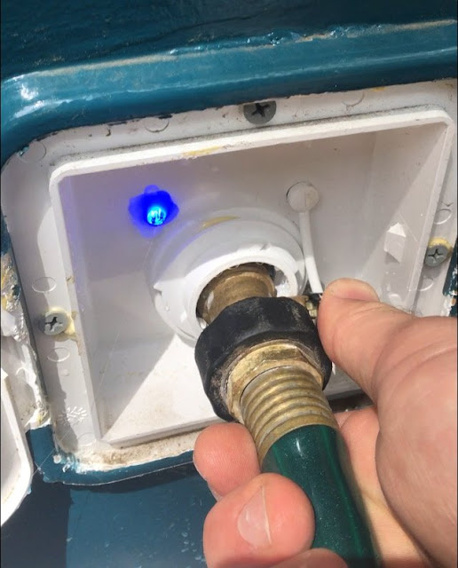
Let's start from the beginning. I fill my water tank up in my driveway with a hose at the tank's fill port. My tank has a vent that comes up to the same fill port, so normally you'd just fill until water comes out. That seems unnecessarily messy, so I put a Liquid Level Sensor at the base of the vent tube so that when water starts coming up, it'll trigger and let the Arduino know the tanks are full. The code then sets the tank level to whatever the tank capacity is (40 gallons in my case).
But how do I know the tanks are full? Well, when this happens, the Arduino also turns on an LED light at the fill port, letting me know to stop filling.
It's important to note that this system is powered by the same circuit as the water pump. I usually leave the water pump circuit breaker off unless I'm actually on the bus (to prevent leaks and spills, you know?), so I need to remember to turn it on prior to filling.
The flow meter is just past the exit port on the water tank, and prior to the water pump. So anytime water leaves the tank, the flow meter will register it. When that happens, it turns the display on and displays what you were looking at last time it was on (either gallons remaining, flow rate (in gallons per minute), or off). This will stay on for as long as the water is flowing, and for 15 seconds after it stops flowing when it automatically turns off and saves the amount of water left to the onboard memory. The arcade button cycles through the displays (gallons remaining, flow rate, and off), so if it's at night you can just set it to the off display and nothing will turn on--even if you use water--but it will still log all the information.
I originally had a battery powered clock sensor too, so that it could tell me how many gallons of water I was using per day, and how many days I have left at current usage rates before I'd be empty--but that ended up being too complicated and glitchy (a GPS unit would be a better source for time), and unlike those tube-food eating dragon tamers, I don't mind doing the math.
Assembling the Device
The only components that need to be visible are the display and arcade button. I ended up using a router to "thin" out a portion of the 3/4" plywood bulkhead that forms the back side of my electrical control panel, so that it's easily visible when using water at the sink, but more importantly, everyone on the bus will see it and I'll get to show off.
The liquid level sensor is installed in the fresh water vent line. I drilled a hole in the vinyl tubing, stuck the sensor in, and hot glued it in place. The associated LED is poking out of the fill port, also held in place with hot glue. Finally, the flow meter is installed inline with the plumbing as described earlier. That leaves the display, button, and Arduino installed next to each other behind the panel.
The general circuit schematic is pretty simple. I have a 24V power supply (for the water pump), which also powers a 24V to 5V step down converter. This converter then powers the Arduino, the liquid level sensor, and the flow meter.
Let's start with the Arduino's wiring:
ARDUINO PIN - COMPONENT
Vin - 5V converter +
GND - 5V converter -
5V - Display Vin
GND - Display GND
2 - Display CLK
3 - Display DIO
5 - Liquid level sensor signal
7 - Indicator LED
9 - Arcade button LED
12 - Arcade button circuit
GND - Arcade button circuit
13 - Flow sensor signal
Those are all the wires coming into and out of the Arduino itself. The liquid level sensor and flow meter's + and - power supply is attached directly to their respective posts on the 5V converter, and the ground pin for the two LEDs return to the - post on the converter.
Arduino Code for Liquid Flow Meter
[The code snippet exceeds the post character limit; the code and description is formatted and available here: https://theargobus.blogspot.com/2020...low-rate.html]
Calibrating the Liquid Flow Meter
The flow meter says each pulse is 2.25 ml, and if you need greater than 10% accuracy, calibration is necessary. I also wanted to see what my full capacity was, so I filled the tank up to max, put a gallon jug under the sink, and started filling.
I had my laptop plugged in to the Arduino so I could see what the pulse value was, and logged this for each gallon that came out of the pipes. As I drained the jug, which I had already marked for increments of 1/8 gallon, I updated a spreadsheet with the number of gallons I had removed, and the number of pulses registered. This took a solid hour of filling, draining, logging. I was extremely happy I had installed an air conditioner for the inside, and had that running the whole time.
Toward the end, I could tell there was less water pressure due to how long the water pump was running. After 36 gallons, it started running continuously, which told me I had reached the end of my tank's capacity. So basically, I knew exactly how much water had flowed through the sensor (36 gallons), and how many pulses the sensor registered (75,807).
It's important to note that once the pulse value registers 65,536 pulses it resets to 1 due to the size of an "int" variable.
75,807 pulses * 2.25 ml per pulse is 170565.75 milliliters that passed through. That's 45 gallons, which is far more than what actually came out. To find the calibration value, we simply divide 36 over 45, which is .8 on the dot.
As a final test, I updated the code with this calibration value, filled up another gallon jug, and verified that the display showed me that I had used exactly 1.0 gallons of water, which it did.
So now I have a precise method of determining exactly how many gallons of water I have left in the tanks, without any float switches or expensive components, all for under $100!
It's also important to note that the decimal lights are inop, so I just pretend they are there. These photos show 33.7 Gallons remaining, 94% full, and 0.0 gallons per minute.
Common Gotchas
- Calibrating is a must, even if you don't care about 10% accuracy. Mine was off by 20%, which is far too much and not worth the hassle
- Installation of the Arduino is key, as well as securing all the wires so they don't come loose. I used hot glue and heat shrink for the tiniest jumper wires, and for everything else I used proper crimps
- Not installing your water tanks correctly. If I fill up in my level driveway, I'll only get about 36 gallons in the tank. But if I fill up at a station, with a slight angle upward, then I'll be able to fill that trapped air pocket in the back and get more. In other words, the "tank capacity" is only as useful as your tank's installation
|
|
|
|
|
04-26-2020, 02:41 PM
|
#131
|
|
Bus Crazy
Join Date: Aug 2019
Location: Moved to Zealand!
Posts: 1,517
Year: 2002
Coachwork: Thomas
Chassis: Freightliner FS-65
Engine: 7.2L Cat 3126 turbo diesel
Rated Cap: 71 passenger 30,000 gvwr
|
Since you mentioned the U-2 and it's on-board fuel computer I couldn't help but decide to provide you a link to the awesome on-board computer system used. They're still used today --I keep my army issued one as a memento...
https://en.wikipedia.org/wiki/E6B
The fuel cell can only measure amt remaining at any given time -- you the operator have to decide the quantity of fuel you're using based on speed, winds, altitude, etc.
I appreciate what you're trying to create with the Arduino and sensors.
I guess the need for it is relative to how difficult it is to manually observe the tanks. You've made me realize depending on how I locate my fresh water tanks they could indeed be less easy to monitor than in the camper I used to live in...
|
|
|
|
|
04-26-2020, 07:00 PM
|
#132
|
|
Bus Nut
Join Date: Apr 2018
Posts: 421
|
All I can think of when I see that old school whiz wheel is that people used to be super smart.
I really enjoy finding different things that could be implemented with an Arduino or Raspberry Pi. Like if you can quantify/digitize any bit of information, what can you extrapolate from that? Back before I realized just how much work this conversion would be, I had this idea that I'd get a triple axis accelerometer, compass, and gyro hooked up to a pi with a GPS, and I'd have different gauges/screens telling me what my heading is, pitch/roll, g forces in each axis, in such a way that I could plot my pitch relative to my elevation as I climb the Sierra Nevadas....
until I realized I'm just happy that the ceiling lights only flicker a little bit and the time it would take to build such a device is time that simply does not exist.
|
|
|
|
|
04-26-2020, 07:45 PM
|
#133
|
|
Bus Crazy
Join Date: Aug 2019
Location: Moved to Zealand!
Posts: 1,517
Year: 2002
Coachwork: Thomas
Chassis: Freightliner FS-65
Engine: 7.2L Cat 3126 turbo diesel
Rated Cap: 71 passenger 30,000 gvwr
|
Quote:
Originally Posted by TheArgobus
All I can think of when I see that old school whiz wheel is that people used to be super smart.
I really enjoy finding different things that could be implemented with an Arduino or Raspberry Pi. Like if you can quantify/digitize any bit of information, what can you extrapolate from that? Back before I realized just how much work this conversion would be, I had this idea that I'd get a triple axis accelerometer, compass, and gyro hooked up to a pi with a GPS, and I'd have different gauges/screens telling me what my heading is, pitch/roll, g forces in each axis, in such a way that I could plot my pitch relative to my elevation as I climb the Sierra Nevadas....
until I realized I'm just happy that the ceiling lights only flicker a little bit and the time it would take to build such a device is time that simply does not exist.
|
Imagine how I feel picking up my ol' whiz wheel and thinking -- I used to know how to use this thing -- and QUICKLY and now I just look it at...
I really appreciate seeing the level of work being done in some of these builds and the work around's to problems I hadn't even considered...
In my ol' camper the ~25 gal fresh water tank sat under one of the dinette booths so you just lifted the bench bottom to see how much water remained.
And when winter came I stopped using it altogether and lived outa 5gal jugs just like when doing river trips...
So until I saw all you went to here I hadn't even considered how "buried under the bus" most peoples tanks are. If you don't have a good idea of your water budget it would be very hard to know how long your waters lasting.
But after a month of living off grid I had a very good idea how long my batteries lasted, and how much lp, and water we went through in a week...
|
|
|
|
|
04-26-2020, 10:59 PM
|
#134
|
|
Bus Geek
Join Date: Sep 2015
Posts: 3,856
Year: 2002
Coachwork: Thomas Built Bus
Chassis: Freightliner FS65
Engine: Caterpillar 3126E Diesel
Rated Cap: 71 Passenger- 30,000 lbs.
|
I used to keep a little plastic slide rule in the glove box of my car to calculate fuel mileage. I probably still have it along with a Post slide rule that used to be my father's slide rule when he was in college studying for his degree. I had a professor that said he could calculate an answer to an electrical problem faster than we could using our handheld electronic calculators verses his slide rule. He proved it all the time. I started using the old Post soon after that and only used the scientific handheld electronic calculator for the trig functions.
|
|
|
|
|
05-05-2020, 04:16 PM
|
#135
|
|
Bus Nut
Join Date: Apr 2018
Posts: 421
|

How to Build a LiFePo4 Battery Bank for your Skoolie
Note: this post is a series on the electrical system. Please view the previous post here to get caught up.
We now know how electricity works (for dummies) and are ready to finally build it out. It's important to note that what I've done here is not the right way to do it--it's simply the way I did it, and I do not recommend anyone build their own electrical system without first researching on their own or consulting professionals. Faulty electrical components, wiring, and batteries can start a fire and absolutely wreck the entire bus. Don't be dumb and take what I say here as any sort of professional advice. It's not. I'm just a dummy who cobbled together a pretty sweet system.
How to Plan a LiFePo4 Battery Bank
Lithium Iron Phosphate (hereafter referred to as simply "lithium") is an excellent battery medium because it can discharge all the way with little damage, it can charge pretty fast, and it can hold its charge for an extremely long time. Since my ultimate goal with Argo is to attend Burning Man for the full nine days in the Black Rock Desert, I absolutely need air conditioning--and since I don't want a generator, I need a solid battery bank with an equally solid solar farm too.
Fortunately for me, a colleague of mine lives on a 40 foot toy hauler with his family of four. He runs his full house load (television, washer/drier, air conditioning, dish washer, etc...) off his battery and solar bank. He doesn't have a generator. He doesn't plug in to shore power. The way he did this is he imported a **** load of lithium pouches that required him to visit customs in LA in order to prove that he wasn't a business. He sells them on the side too, which is how I came to acquire 40 of these pouches for ~$20 a piece.

Each pouch is rated for 3.2V and 30 amp hours (note: the wider tab is the positive tab) and is about the size of a small notebook. Stack these together in series and parallel, and you can get the desired battery bank. Essentially, I made a giant battery using these pouches and cables. Take apart many commercial lithium batteries and they do something similar, only much better than I ever could.
For all the great things about lithium, there's one major drawback: each pouch is ever so slightly different than another. One may discharge slightly faster, or another might not be able to hold as high a voltage as the rest. These means you need balancers that detect which pouches are different, and rectifies the imbalance.
If this imbalance remains, then it's possible that you will overdischarge a single pouch (or cell) while all the others discharge to the normal voltage. The other major drawback for lithium cells like these is that if a cell drops below its minimum voltage, the cell will be permanently damaged. Likewise, if a cell's voltage exceeds its maximum voltage capacity, the cell will be damaged. To protect against this over discharge and over charge state, one needs a battery management system. This goes in between the battery packs cathode (the most negative part) and the rest of the electrical system, and has a wire for each "cell" of the battery pack. If it detects any of the cells' voltage outside the normal range (in my case, 2.2-3.75V) then it will cut off the battery pack until it gets exposed to a safe voltage level (2.7V and 3.55V). It also balances the cells for added protection.
I already know I want a 24V system (see the previous post), and if each pouch is 3.2V, then I need to hook up 8 of them in series.
Let's do a quick refresher on that. If you wire batteries up in series, you increase the voltage (the potential energy, or the electrical "pressure"). If you wire the batteries up in parallel, you increase the amp-hours capacity (the actual juice that's able to squeeze out). You can combine these two to get your desired battery pack.

Batteries wired in series (which increases voltage)

Batteries wired in parallel (which increases amps)
Let's keep it simple in this case. Each pouch is 3.2V, and I want 24V total, so I simply divide 24 by 3.2 and get 7.5 pouches necessary. Obviously I can't have a half pouch, so I round up to get 8 pouches, so now my pack voltage is 8 * 3.2 = 25.6V.
Now you might say, "That's not 24V! It'll ruin my system by frying my electronics with all that extra voltage!" But remember, the voltage is just the electrical pressure pushing the current out, not the actual current. What determines the current is the device itself. So have a voltage slightly higher than the "rated" voltage is actually desirable because the voltage, on average, should be the rated voltage. That means that a fully charged battery pack will actually exceed the rated voltage. A 24V system is actually more like a 28V system at maximum charge, and an 18V system at maximum discharge.
Okay, so back to the batteries pouches. I have 8 of them hooked up in series, meaning one pouch's positive tab is hooked up to another's negative tab. This is represented as an "8S" pack, since I have 8 in series. I would then connect the BMS's monitoring wires to each cell's positive anode (which would also be connected to the next cell's cathode).
Each pouch is 3.2V and 30 amp hours. If I have 8 of them hooked up in series, now my battery pack is 24V and 30 amp hours, or measured in watts (the preferred method, in my unprofessional opinion), 720 watts (or watt-hours to be precise, but I'm not being precise here). Based on my previous post, I determined that I need about 800 watts per day, so this simple battery pack would be enough for one day off-tether.
I've used only 8 of my 40 pouches, so I have 32 remaining. How do I add them? Well, let's revisit my battery pack. It has 8 cells wired in series, and each cell only has 1 pouch. How would I add another pouch to each cell? Well, to make it easier to understand for dummies like me, I think of it in terms of cells.
Each cell must have 3.2V. Now, it can have one pouch, or a hundred pouches, it doesn't matter--just as long as its voltage is 3.2V. So if I take two pouches, and connect them in parallel (meaning, I connect their positive tabs together, and their negative tabs together), the cell's voltage is still 3.2, but now the cell's amp hour capacity has double to 60. The positive anode of the cell now consists of both positive tabs of the two pouches. In other words, now I have 8 different cells, each one consisting of 2 pouches that are hooked up in parallel. Each of these 8 cells are 3.2V and 60 amp hours. If I connect these cells together in series (meaning, I wire one cell's positive anode to the next cell's negative cathode), the amp hours stays the same, but the voltage increases to 24V. So now my battery pack is 24V with 60 amp hours, or 1440 watts. This is represented as 8S2P, meaning I have 8 cells in series, and 2 in parallel.
I have 40 pouches, and I already know that I'll have 8 different cells in order to get 24V. So I simply divide 40 by 8 to get how many pouches each cell will have, which leads me to 5 pouches wired together in parallel in each cell, or 8S5P. This gives me a grand total of 24V and 3600 watts. The BMS has a wire for each cell (so 8 wires) PLUS a black wire for the battery's master cathode (labeled as B-) in order to actually measure what each cell's voltage is. When one cell gets out of wack, it will balance or cut off electricity output in order to protect the cell.
So far, the master battery pack, which I'll just refer to as "the battery," consists of 40 pouches, wired in an 8S5P configuration, and protected with a BMS that is wired to each of the 8 cells. The last thing I want to add is a master battery cutoff switch that I can flip at the battery itself, so I can remove all electrical power to the electrical system from the source. I included this switch after the BMS, such that there are two posts that leave the battery. One is the positive anode, which is sometimes referred to as B+. This anode/post is directly connected to the most positive tab of the battery pack. The other is a negative cathode (B-), which is then connected to the cutoff switch, which is then connected to the BMS, which is then connected to the most negative tab of the battery pack.
What about the balancers? Well, the balancers I bought to accompany the BMS work GREAT, but they also emit a high pitched ringing sound when they work correctly. If I had a full size bus with undercarriage storage for the batteries, this would be fine, but since the batteries are in the cabin, the sound is unfortunately irritating. Since the BMS does some balancing too, I decided to just create a "balancing board" with all the balances attached, and when the bus sits in my driveway for extended periods of time, I hook up this balancing board to keep the cells happy when no one is in there to hear the ringing.
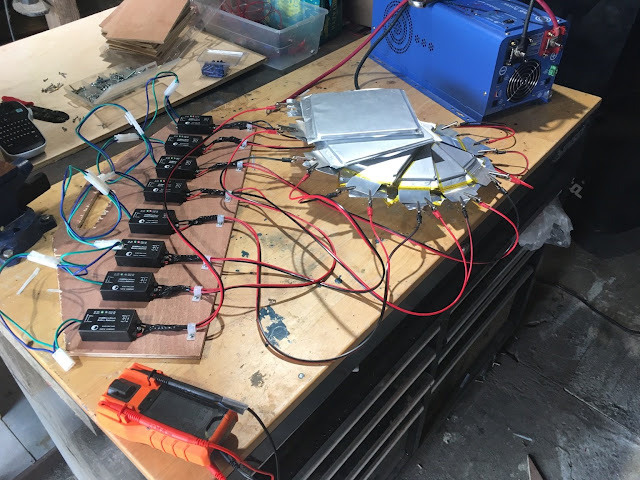
Here's a few photos of me balancing the cells individually before putting them in the pack. I used my AIMS inverter/charger to charge at the lowest charge current so that the balancers could do their thing as efficiently as possible.
Balancing an 8S1P pack
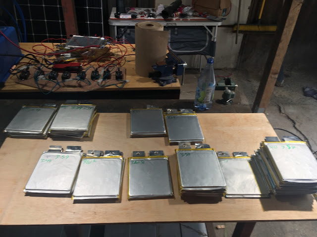
Dividing them up based on their voltage, down to .01V
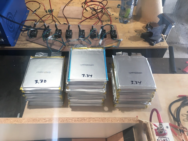
Dividing them up into three groups: the lowest, middle, and highest charges
How to Contain LiFePo4 Pouch Cells
The cells are known to sometimes expand in rapid discharge situations, so they must be "contained" in such a way that they are compressed and won't expand too much if this happens. I also want it to be in it's own "box" so to speak like a commercial battery solution to keep it well contained and to make removing it easy.
I simply used 3/4" plywood to make a container that holds all the pouches tightly together. It includes handles for ease of use, and a panel with easily accessible posts for the outgoing electrical connections which also contains the battery cutoff switch. Lastly, the BMS is simply attached to the side of this box, such that the BMS will always accompany the batteries no matter if I turn the master battery switch off or remove them altogether.
Since I'm space-limited, I squeezed all 5 pouches of each cell together, and have a thin piece of plywood with a plastic divider in between cells to keep them compressed and separated.
How to Wire LiFePo4 Pouch Cells
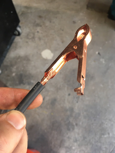
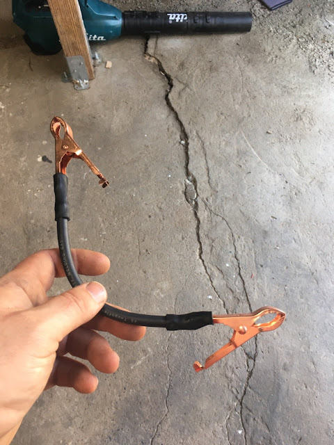
The proper way is to weld the tabs together or to high gauge wire to then connect to other tabs. Since I'm an amateur, I did not go this route and instead used battery clamps and 6 AWG wire to connect the pouches/cells together.
What size of wire do you need? I used this calculator. I have 24V, but how many amps should I use to calculate the wire size? Well, this is kind of hard, since I don't really know if I'll ever use any high amp items in the future. So I just used my inverter/charger rating of 2000W to determine that, at 24V, I'd be drawing 83 amps. Basically, that means if I ever use the inverter at its max capacity, it'll be sucking down 83 amps through the wires out of the battery pack.
What about wire length? Well, the wires inside the battery pack are only a few inches long. But the wires going from the battery pack to the electrical control panel would need to be six feet long, so I used that to keep everything consistent. And how about voltage drop? It seems that 2% is the standard, but since I want to maximize efficiency, I went with 1%.
Once I put all that in, it says that I need at least 6 AWG wire (meaning, an AWG rating of 6 or lower, which corresponds to a thicker wire). What this tells me is that if, at some point in the future, I am using the inverter at its max capacity, everything will be fine as long as the electrical cabling is 6 AWG.
Unfortunately, that's pretty thick, so I can't use a regular wire crimp tool. It requires a special welding cable crimper, heavy duty crimps, and heat shrink. That's fine--as I alluded to in the previous electrical post, I'm okay shelling out money for high quality electrical components and tools.
So now I know that the wiring/cable will be 6 AWG, hereafter referred to as "cable." Now how do I connect this cable to the battery pouch tabs?
I used battery clamps and dielectric grease. The grease acts as a slight adhesive between the battery tabs of each specific cell, and also ensures a good conductive contact. The battery clamp holds the tabs together, and is connected with the 6 AWG cable to the next battery clamp, which holds the next cell's tabs together.
The best battery clamps I could find, especially in these coronavirus times, were at Home Depot and are rated for 30 amps. That means that anything above 30 amps exceeds the rated capacity for these clamps, which is determined by the thickness and type of metal. So now I'm not just limited by the max amperage pull of the cable, but actually by the amp rating of these clamps. 30 amps at 24 volts is 720 watts, meaning if I pull more than 720 watts, I risk overheating/melting/igniting these clamps.
This is a risk/limitation that I'm willing to accept. In what scenario would I pull more than 30 amps of 24V DC power? I'm not living on Argo full time. I don't have a hair drier. The biggest electrical pull, by far, will be the air conditioner, which pulls 475 watts from the battery bank (determined through testing in my driveway). If the refrigerator is also running (70 watts) as well as the water pump (100 watts), and a phone charger (30W), I'm only drawing 675 watts. Remember, my worst case scenario, daily wattage is 800W spread throughout 24 hours. And on top that, we wouldn't be running the air conditioner unless we're in sunlight powering my 900W of solar panels, which would decrease the battery discharge current significantly.
I acknowledge that this is the weakest point in my whole electrical system--the fact that the method through which I connect my battery cells together is limiting my whole electrical draw to 30 amps. However, I don't see any situation where I'd even be drawing more than 15 amps--Argo is simply a weekend trip boondocking vehicle, not a full time home. As I said before, this is a limitation and risk that I am willing to accept. The best I can do is match the inline fuse rating to the same as the battery clamp rating, such that if there's a short or a draw that exceeds 30 amps, the fuse will blow and prevent that current from leaving the batteries.
How do they stay connected to the tabs? Well, I used dielectric grease to "stick" the five tabs together, and then I used the battery clamp to assist in holding them together. The springs in the clamp are quite strong. After ops testing a few hour long trips, I've noticed that the clamps don't budge after being on the road. There really isn't a whole lot of force acting on them that would overcome the springs in the clamps. In any case, I still have installed these plastic "shims" in between the cells that will prevent the clamps from accidentally crossing over in the even they unclamp. If they were to unclamp, it will break the electrical circuit, and will be identical to turning the master battery cutoff switch to off. This will be noticeable immediately, but will not cause any damage other than to my ego.
To connect the clamps to the cable, I stripped the cable and inserted the raw wire into one side of the clamp and crimped it with the crimper tool. I then used the butane torch to heat shrink it for protection and to keep it together. These cables aren't very long--maybe a few inches or so. Once I attached them together, I used the crimper tool and the lugs to connect the B+ cable to its post, and the B- cable to the BMS, and then again from the BMS to the cutoff switch, and then again to B- post. It's important to note that the cutoff switch has a third position, which bypasses the BMS altogether in case it malfunctions, as I've been having issues with the BMS erroneously tripping its protection circuit.

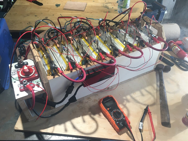
With the Balancing Board attached
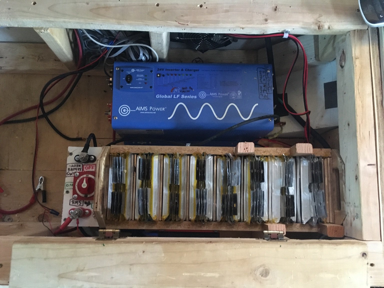
How to Install a LiFePo4 Battery Bank in your Skoolie
So now we have a self-contained battery unit, with an integrated protective BMS, two easy to access posts for the anode and cathode, and a master battery cutoff switch. To install this beast in the bus, I had to consider not just where everything else would go (inverter/charger, outlet, shunt, ANL fuse, etc...), but also what would happen if the bus rolled? Having this battery fly out the seat would be disastrous and could potentially start a fire. So in my electrical compartment, which I call the E-Bay, I routed a notch in the seat framing to hold the battery down, and for the other end drilled a 2x4 to the battery pack panel and another 2x4 that's part of the seat frame. The last protective feature I installed is a plexiglass covering that protects the battery pouches from dropped objects. If the seat is closed or partially open, and I drop a screw, and that screw falls down and creates a short between two tabs, it'll cause a massive headache. To prevent this from happening, the plexiglass covering essentially prevents any items from dropping on the pouches, but still lets me see the status of the clamps and connections.
The rest of the electrical components will be covered in future posts.

Common Gotchas
- Not sizing the wires correctly. Think about how many amps you plan on using at max draw, and get the right sized wire. This is kind of related to the issue with my battery clamps being rated for 30 amps--now I know that I cannot exceed 30 amps from my battery bank, or else I risk having the clamps fail. But then again, I don't really know how else to connect the tabs together given the size restraints of having a shorty
- Balancing the cells--these lithium pouches must be balanced to within .1V of each other, otherwise they'll start discharged and charging at different rates and reduce the overall capacity
- Get the right protective equipment--the master battery cutoff switch is great for when I'm working on the electrical system and need to cut power off at the source. The BMS is there to protect this whole investment, as well as the balancers
|
|
|
|
|
05-05-2020, 06:51 PM
|
#136
|
|
Bus Crazy
Join Date: May 2010
Location: Farmington Hills, Mi (Detroit area)
Posts: 1,968
Year: 2000
Coachwork: Eldorado Aerotech 24'
Chassis: Ford E-450 Cutaway Bus
Engine: 7.3L Powerstroke
Rated Cap: 19
|
Awesome how-to!!!!!
I want to build one now.
|
|
|
|
|
05-05-2020, 11:21 PM
|
#137
|
|
Skoolie
Join Date: Jul 2015
Location: Vermont
Posts: 152
Year: 1996
Coachwork: Turtle Top
Chassis: E-Super Duty
Engine: Ford 7.3 Powerstroke
Rated Cap: 13-passenger
|
Quote:
Originally Posted by TheArgobus
Back before I realized just how much work this conversion would be, I had this idea that I'd get a triple axis accelerometer, compass, and gyro hooked up to a pi with a GPS... until I realized I'm just happy that the ceiling lights only flicker a little bit and the time it would take to build such a device is time that simply does not exist.
|
I'm building a neat gadget for my truck that crosses off several of these items. Here's the source: https://freematics.com/store/index.p...tegory&path=20
The inspiration for me was that a used compass/thermometer on ebay was more expensive than a full Freematics kit, which provides: OBDII code reading and clearing, OBDII data logging, accelerometer, gyroscope, magnetometer, thermometer, and probably some other things I'm not remembering.
I'll be rigging mine up with a touchscreen and an additional (exterior) thermometer, but that's just what I was looking for. You could do GPS, bluetooth, etc., etc.
Quote:
|
Well, the balancers I bought to accompany the BMS work GREAT, but they also emit a high pitched ringing sound when they work correctly. If I had a full size bus with undercarriage storage for the batteries, this would be fine, but since the batteries are in the cabin, the sound is unfortunately irritating.
|
Have you considered noise cancelling?
https://www.sweetwater.com/store/det...B&gclsrc=aw.ds
|
|
|
|
|
05-05-2020, 11:41 PM
|
#138
|
|
Bus Geek
Join Date: Sep 2015
Posts: 3,856
Year: 2002
Coachwork: Thomas Built Bus
Chassis: Freightliner FS65
Engine: Caterpillar 3126E Diesel
Rated Cap: 71 Passenger- 30,000 lbs.
|
Quote:
Originally Posted by sproutroot
I'm building a neat gadget for my truck that crosses off several of these items. Here's the source: https://freematics.com/store/index.p...tegory&path=20
The inspiration for me was that a used compass/thermometer on ebay was more expensive than a full Freematics kit, which provides: OBDII code reading and clearing, OBDII data logging, accelerometer, gyroscope, magnetometer, thermometer, and probably some other things I'm not remembering.
I'll be rigging mine up with a touchscreen and an additional (exterior) thermometer, but that's just what I was looking for. You could do GPS, bluetooth, etc., etc. |
For those of us with a Can bus (J1939), the interface costs a bit more. Here is the link.
|
|
|
|
|
05-06-2020, 12:28 PM
|
#139
|
|
Bus Nut
Join Date: Apr 2018
Posts: 421
|
I like it... Ive ordered to gps and MPU and already have the raspberry pi and touchscreen and environment sensor. However, this is a 95 E350although it has an OBD-2 style connector under the steering column, Ive never gotten any of my OBd2 readers to work on it. The shop has had some luck but the tech is always gone by the time I ask about it. Perhaps it could be OBD1 or some proprietary ford system? Id love to get data logging or even just error codes
|
|
|
|
|
05-06-2020, 12:43 PM
|
#140
|
|
Bus Geek
Join Date: Dec 2015
Location: pa
Posts: 2,509
Year: 98
Coachwork: 1. Corbeil & 2. Thomas
Chassis: 1 ford 1998 e350 4x4 7.3 2 mercedes 2004
Engine: 7.3 powerstroke & MBE906
|
Nice job on the battery setup. really nice and practical DIY approach.
Johan
|
|
|
|
|
|
 Posting Rules
|
You may not post new threads
You may not post replies
You may not post attachments
You may not edit your posts
HTML code is Off
|
|
|
|
 » Recent Threads
 |
|
|
|
|
|
|
|
|
|
|
|
|
|
|
|
|
|
|
|
|
|
|
|
|
|
|
|
|
|
|
|
|
|
|
|
|
|


 Linear Mode

