 |
|
 05-08-2020, 11:42 AM
|
#141
|
|
Bus Nut
Join Date: Apr 2018
Posts: 421
|

How to Choose and Inverter/Charger for a Skoolie
Note: this post is a series on the electrical system. Please view the previous post here to get caught up.
I have my battery box built and ready to go. Since Argo primarily sits in my driveway, the main way to charge the batteries will be shore power, followed by solar (at some future date). I also need an inverter (which takes DC and turns it into AC) to power the air conditioner (and maybe a laptop or two). Since I'm space limited, I need to combine the two to tuck the whole electrical system into one compartment (the "E-Bay"). Fortunately, inverter/charger combos are quite common, but the big thing I had to decide was what type of inverter to get.
There are three types of "waves" one can get in an inverter: pure sine, modified sine, and square. All AC power comes in waves--this is a consequence of how it's generated using rotating machinery, whether through a water paddlewheel, a windmill, or an engine alternator. This can be visualized below:

The sine wave on the right represents how fast the electrons are moving out, then moving back in, and back out, and back and forth. This may or may not be literally true, it's just how I visualize it. DC, on the other hand, only moves in one direction. Because of this, when you convert this one-directional direct current into bidirectional alternating current, it usually comes out as a blocky, modified sine wave:
Most cheap inverters go this route with a modified sine wave. The upside is that they're cheap; the downside is that for some AC components (especially those with motors, such as fridge compressors and air conditioners) they need more modified sine wave AC to do the same work as they would with a pure sine wave. Meaning it's about 20% less efficient than a pure sine wave inverter.
What about square? Well, I'm not going to bother with this one. Don't get a square wave inverter.
A pure sine wave inverter costs more, but its AC output is much smoother, more consistent, and is exactly what AC appliances are designed for. So I went with a pure sine wave inverter/charger.
As already discussed in my previous posts, I have a 24V system, and my friend who sold me the batteries recommended AIMS Power for my inverter. Since my AC electrical needs are quite meager (it's just the 450W air conditioner), I went with the smallest 24V inverter/charger they had at 2000W. Because my battery clamps are limited to 30 amps, I know that I won't ever be exceeding 720 watts, so the whole surge rating isn't really important to me. In fact, the most important thing is that this will charge my batteries.
It helps to visualize what's going on here in my setup, which is probably different than yours. If you haven't read the post on my battery pack or the electrical plan, then read those first.
Let's say my battery is fully charged, meaning the voltage is 28.8 (remember, voltage is just the electrical "pressure" or potential electrical energy available). The positive terminal is wired directly to an inline fuse, which is then wired directly to both the DC distribution panel (which powers the lights, water pump, fridge, heater, and fans) and the positive terminal of the inverter/charger. The negative terminal of the battery is wired directly to the shunt, which is then wired directly to the DC distribution panel and the negative terminal of the inverter/charger. This allows the inverter/charger to "sense" what the battery voltage is, and since it's fully charged, it will just monitor.
If, say, the water pump is running, it draws electricity from the battery bank, which now experiences a voltage drop since it's pushing out electricity. When the inverter/charger senses the battery voltage is now below a certain threshold, it now knows that the batteries are no longer fully charged, and need charging. For the AIMS 24V 2kW inverter/charger I have, it will push out 25 amps of charging current at 28.8V. Now obviously it's not actually pumping 25 amps into the batteries whenever it charges; the actual amount of current is metered depending on the battery's voltage. In this example, it will only push out a small amount of current to keep the batteries fully charged.
If we leave the pump on, and turn everything else on, the battery will lose more voltage, which then triggers the inverter/charger to push more electricity out of its positive and negative terminals. But since these terminals are also connected to the DC distribution panel, which now has quite an electrical demand, some of the charging current coming out of the inverter/charger goes directly to power the DC distribution panel. The batteries are still getting charged, it's just now their getting less current because some of it is going to the DC load. The inverter/charger doesn't know this, it just sees the voltage--if the voltage is low, it keeps pumping out charging current until the voltage is high--and if the voltage is high, it doesn't do anything. In this way, the inverter/charger not only charges the batteries, but it also powers the DC distribution panel! (Only if plugged in to shore power, obviously).
Now let's plug in a margarita blender to the outlet (while we're still plugged in to shore power). AIMS has a relay set up in the inverter such that, if there's an AC draw from the outlet, it will power it directly from the shore power plug and bypass the inverter function. This is great because it won't bother the batteries if plugged in.
Let's unplug from shore power. Now the inverter senses that there's an AC load from the outlet, and draws 24V DC power in from the batteries, "inverts" it to 120V AC, and powers the margarita blender this way. The process of inverting electricity isn't 100% efficient. A good rule of thumb for planning is to expect a 20% loss in the inversion, but I've ops tested this and it's a more like a 5% loss. Meaning in order to produce 450W AC out of the outlet, it will draw in 475W DC from the batteries.
How to Hook Up Shore Power in a Skoolie
Most RV sites use circular 30 or 50 amp plugs to provide "shore power" to the RV. This is for the big, full size RVs that have massive electrical demands, such as washers, driers, TVs, microwaves--all at the same time. Although my electrical needs are quite meager, I still went with the standard 30 amp hook up/plug because that's the standard at RV parks around the country. I don't have one of those at my house, but I do have a regular outlet, so I picked up a regular wall plug to 30 amp inlet adapter.
I cut a hole in the wall of the bus to slide the plug into, using automotive seam sealer to set it. Then I installed the 10 AWG triplex wire, which goes from the plug to the AC input on the inverter/charger.
It's important to note the three types of wires here: there's the hot/phase/line (black), neutral (white), and ground/earth (green or bare metal). The hot line is where the action takes place, pushing the electrons back and forth as mentioned above. They push against the neutral wire, which is necessary to be, well, neutral. Lastly, the ground is a protective circuit that will protect against loose wires that come into contact with things they're not supposed to. This is a very dumbed down version of AC power that helps me understand, and is not to be taken literally (or figuratively).
So now the charger function works, so long as it's hooked up to a battery. In my setup, I have the positive cable from the charger hooked up to the second post of the inline fuse (the battery is hooked up to the first post) and the negative cable is hooked up to the second post of the shunt (the battery is hooked up to the first post). Now I can charge my batteries.
How to Wire an Outlet in a Skoolie
An outlet needs four things: triplex wire, an electrical box, the actual outlet itself, and the protective plate/covering. I just picked up the most basic "old work" style electrical box to keep it simple and cut an appropriately sized hole in the wood paneling. I then used a screwdriver to tighten the screws on the box, which spins and pulls a plastic tab into place on the back side (behind the wall), and that holds the whole box tight against the wood panel. I then ran the triplex wire from the AC output on the inverter/charger through the opening on the back of the box and pulled it out from. It's pretty straight forward from here: I stripped the wire bare, wrapped it around its respective screw on the outlet, and then eased the outlet into place, taking care not to accidentally push or pull a wire off its post. I then screwed the outlet into the box, took one last look to make sure the wires were still connected, then put on the stainless steel protective plate.

Now all I have to do is turn the inverter/charger on, plug something into the outlet, and voila! I have a working 120V AC outlet in my skoolie. In fact, I have only this one outlet, right in the middle of the cabin. It has two USB slots, including a USB-C for laptop charging, and I really don't see myself using it for much. Especially if I'm self-limiting to 750W of power. But at least it's there.
In addition to the triplex AC output, the inverter/charger also has a built-in GFCI outlet on the unit itself. What the heck is GFCI? It stands for ground fault circuit interruptor, which essentially cuts off power if it detects a fault or a short. These outlets have two buttons: test, and reset. If it trips, you have to hit the reset button and you'll hear and audible click. I plugged an extension cord into my GFCI outlet, and ran it behind the seats and up to the ceiling, where it's plugged into the air conditioner and has a few other sockets available.
So now we have a fully working 120V AC system on the bus that also charges the batteries!
Common Gotchas
- In my humble unprofessional opinion, I really think a pure sine wave inverter is the only way to go. I think it's one of those "you get what you pay for," things where if you get the cheaper tool now, you'll end up paying the price later
- The right gauge of wire is necessary for skoolies! Think about what they'll be exposed to; heat, spilled liquid, maybe road debris if outside. It isn't just the wire gauge that's important, it's the protection sheathed around the cable too
- In my opinion once again, I think it's better to go DC as much as possible. Not only will it be more efficient (thus saving you battery life), but it will be simpler to wire everything up with DC than AC. Which brings me to one last point: if you have AC outlets anywhere in your skoolie, ensure they are powered by the inverter instead of being wired directly to the 30-amp RV inlet. This isn't just less wiring overall, but it's safer too!
|

|

|
|
05-08-2020, 01:41 PM
|
#142
|
|
Skoolie
Join Date: Jul 2015
Location: Vermont
Posts: 152
Year: 1996
Coachwork: Turtle Top
Chassis: E-Super Duty
Engine: Ford 7.3 Powerstroke
Rated Cap: 13-passenger
|
Nice write up. I love this thread.
My wiring is completely different than yours and honestly less convenient, but I wonder why you're saying it isn't SAFE to have an AC circuit connected directly to shore power? I have just such a circuit, and the fusing and wiring and outlets are identical to my inverter circuits, so this doesn't make sense to me. Seems to me, if you have an opportunity to avoid using your expensive sine wave inverter, you should take it.
I read a lot about full timers using cheaper inverters for the bulk of their needs, and a sine wave inverter for a few key outlets. Not only do they get away with small, inexpensive sine wave inverters, but they last forever because they're rarely used.
|
|
|
|
|
05-08-2020, 02:15 PM
|
#143
|
|
Bus Nut
Join Date: Apr 2018
Posts: 421
|
Quote:
Originally Posted by sproutroot

Nice write up. I love this thread.
My wiring is completely different than yours and honestly less convenient, but I wonder why you're saying it isn't SAFE to have an A/C circuit connected directly to shore power? I have just such a circuit, and it goes through identical fusing and wiring and outlets as my inverter circuits, so this doesn't make sense to me. Seems to me, if you have an opportunity to avoid using your expensive sine wave inverter, you should take it.
I read a lot about full timers using cheaper inverters for the bulk of their needs, and a sine wave inverter for a few key outlets. Not only do they get away with small, inexpensive sine wave inverters, but they last forever because they're rarely used.
|
Thanks! I'm writing this with me as the target audience (what I wish I would've known going in), and what I'm really trying to say is that having two separate AC circuits at the same time (one from the inverter, one directly from shore power) is less safe than having a single AC circuit running from the inverter (not that it's unsafe). I say that because I have a bit of experience with sailboats and living aboard, and most discussions come to the same conclusion. See this one here ( https://www.cruisersforum.com/forums...ts-184771.html). It's doable, it's just it unnecessarily presents shock hazards in certain situations. Keep in mind I am not an electrician and am basically repeating what others have said, I'm not 100% sure I follow the reasoning but I'm okay just keeping it simple. Perhaps someone with more knowledge can chime in here.
|
|
|
|
|
05-08-2020, 03:51 PM
|
#144
|
|
Skoolie
Join Date: Jul 2015
Location: Vermont
Posts: 152
Year: 1996
Coachwork: Turtle Top
Chassis: E-Super Duty
Engine: Ford 7.3 Powerstroke
Rated Cap: 13-passenger
|
Did you see that John61ct came in and corrected everyone at the end of that thread? hahahaha the guy's everywhere!
The OP of that thread was talking about a bad strategy - I agree, but I think your impression of the resolution was wrong (understandable, there was a lot of argument before it got resolved).
basically, the thread came down to this - and it was my understanding as well: "Circuits cannot be fed by a neutral connected to ground at different sources."
in other words, running multiple power sources at the same time (whether multiple AC sources, or AC + DC sources, or multiple AC/DC voltages, etc.) doesn't affect anything assuming each sources' current carrying circuits are isolated.
|
|
|
|
|
05-08-2020, 04:48 PM
|
#145
|
|
Bus Nut
Join Date: Apr 2018
Posts: 421
|
Whelp I am a dummy. I investigated why I always considered that unsafe, and what it actually is is when you have an AC control panel and hook up both the inverter/charger and shore power at the same time.
Having separate AC circuits, powered by different sources, is just fine. In fact, I plan on having a circuit that's only powered by shore power (it will charge a jump start battery and power tool battery charger in my toolbox, things that I want to have topped off before I leave but don't want to drain my batteries).
|
|
|
|
|
05-08-2020, 04:49 PM
|
#146
|
|
Bus Nut
Join Date: Jul 2019
Location: California, Bay Area
Posts: 896
|
Quote:
Originally Posted by sproutroot
basically, the thread came down to this - and it was my understanding as well: "Circuits cannot be fed by a neutral connected to ground at different sources."
in other words, running multiple power sources at the same time (whether multiple AC sources, or AC + DC sources, or multiple AC/DC voltages, etc.) doesn't affect anything assuming each sources' current carrying circuits are isolated.
|
I think this is one of the advantages of an inverter/charger. It handles the details of this for you.
As I understand the issue--and my understanding is extremely elementary and shaky--is that there should be only one point (at a given time) where Neutral is bonded to Ground, and one system grounding point. The trouble arises because system ground point should be the battery negative terminal when your vehicle is 'floating' and should be the shorepower connection when connected to shorepower.
I think, and I'm not totally up to speed on the details, ArgoBus's solution is to basically use the shorepower connection as a 'battery charger' as opposed to how RV's traditionally use it to supply power to the AC electrical system directly. I can connect with this approach, the simplicity intuitively feels safer, not necessarily because it is safer at a technical level, but because it allows less opportunity for us layfolk to screw something up in design or installation. And for more systems with modest power needs this is probably a more than acceptable solution.
However inverter/chargers are probably a more elegant solution, especially for larger or more power hungry builds. They will internally switch the neutral-ground bond automatically depending on whether they are in inverting or charging mode. One of the advantages of this is that you can have AC circuits that are powered off shorepower only.
As I said, I don't have any real experience in this area, and limited knowledge, so I might well be misunderstanding something or overlooking something.
|
|
|
|
|
05-08-2020, 04:55 PM
|
#147
|
|
Bus Nut
Join Date: Jul 2019
Location: California, Bay Area
Posts: 896
|
Here are a couple excerpts from inverter/charger manuals that explain the above a little better:
Samlex Evo:
Quote:
|
3.14.1 OUTPUT NEUTRAL TO CHASSIS GROUND BOND SWITCHING
|
Quote:
As required by NEC and UL specification 458, AUTOMATIC Output Neutral to Chassis Ground bond switching arrangement has been provided in these units through “Output Neutral to Chassis Ground Bond Switching Relay” [K4 in Figs 4.1(a) and 4.1(b)] to switch bonding of the Output Neutral Connector of the Inverter Charger as follows:
- When operating as an inverter, the current carrying conductor of the Inverter Section that is connected to the Output Neutral connector of the Inverter Charger is bonded to the metal chassis of the inverter by the “Output Neutral to Chassis Ground Bond Switching Relay” [K4 in Figs 4.1(a) and 4.1(b)]. As the metal chassis of the inverter is in turn bonded to the RV Ground (chassis of the RV) or to the Boat Ground (DC Negative Grounding Bus Bar and the Main AC Grounding Bus Bar are tied together in a boat and this is called the “Boat Ground”), this current carrying conductor of the Inverter Section will become the Grounded Conductor (GC) or the Neutral of the Inverter Section
- When in Charging Mode, the Neutral conductor of the Grid power/Generator will be connected to the Output Neutral connector of the Inverter Charger. At the same time, the “Output Neutral to Chassis Ground Bond Switching Relay” [K4 in Figs 4.1(a) and 4.1(b)] will unbond (disconnect) the Output Neutral connector of the Inverter Charger from the chassis of the Inverter Charger. This will ensure that the Grounded Conductor (GC) / Neutral of the Grid power/Generator is bonded to the Earth Ground at one single point at the location of the AC Power Distribution System of the Marina/RV Park.• Disabling Neutral to Ground Bond: In some applications, the Output Neutral may be required to remain isolated from the chassis/
|
Victron Multiplus:
Quote:
The MultiPlus is provided with a ground relay (relay H, see appendix B) that automatically connects the Neutral output to the chassis if no external AC supply is available. If an external AC supply is provided, the ground relay H will open before the input safety relay closes. This ensures the correct operation of an earth leakage circuit breaker that is connected to the output.
- In a fixed installation, an uninterruptable grounding can be secured by means of the grounding wire of the AC input. Otherwise the casing must be grounded.
- In a mobile installation (for example, with a shore current plug), interrupting the shore connection will simultaneously disconnect the grounding connection. In that case, the casing must be connected to the chassis (of the vehicle) or to the hull or grounding plate (of the boat).
|
|
|
|
|
|
05-08-2020, 05:28 PM
|
#148
|
|
Skoolie
Join Date: Jul 2015
Location: Vermont
Posts: 152
Year: 1996
Coachwork: Turtle Top
Chassis: E-Super Duty
Engine: Ford 7.3 Powerstroke
Rated Cap: 13-passenger
|
I'll try to be a little clearer.
Think of your inverter as a power source rather than a power conditioner. All the current carrying circuits (ie. the hot to neutral circuits) that originate from it lead right back to that inverter.
Because of this, grounds are not current carrying, even though they're bonded to neutral at the source. this makes common grounds between AC power sources okay. There's zero potential energy between them, even if the power sources are out of phase, or at different voltages. When you connect your negative battery terminal to the grounding rod at your house their potentials (theoretically) equalize.
This is a tough topic. I apologize if my description doesn't illustrate it well.
The important thing to avoid is what TheArgobus said above: feeding multiple AC power sources through the same distribution panel at the same time. Doing that would require phase matching, and even then I doubt it's safe.
|
|
|
|
|
05-08-2020, 06:37 PM
|
#149
|
|
Bus Nut
Join Date: Jul 2019
Location: California, Bay Area
Posts: 896
|
Quote:
Originally Posted by sproutroot
I'll try to be a little clearer.
Think of your inverter as a power source rather than a power conditioner. All the current carrying circuits (ie. the hot to neutral circuits) that originate from it lead right back to that inverter.
Because of this, grounds are not current carrying, even though they're bonded to neutral at the source. this makes common grounds between AC power sources okay. There's zero potential energy between them, even if the power sources are out of phase, or at different voltages. When you connect your negative battery terminal to the grounding rod at your house their potentials (theoretically) equalize.
This is a tough topic. I apologize if my description doesn't illustrate it well.
|
It is definitely a tough topic for me to wrap my head around. If this comment was directed towards me, could you clarify if there was a specific part of what I wrote above that you think missed the mark or misinterprets something?
I agree with what you say re: "think of your inverter as a power source" as long as we are talking about the output side. I think I pretty much agree with everything you wrote above, and don't see any conflict between what I wrote and what you wrote. (Also, you did a good job of clearly explaining a semi-complex topic there, just wanted to acknowledge that).
It sound to me like you are talking about the grounding system on the AC output side of things (output side of the inverter, output side of charger), whereas I was referring to the grounding system on the source side of things (i.e. between the inverter and battery, or charger and grid connection). I may have misunderstood what was being discussed, or may still be missing your point.
Quote:
|
The important thing to avoid is what TheArgobus said above: feeding multiple AC power sources through the same distribution panel at the same time. Doing that would require phase matching, and even then I doubt it's safe.
|
Not to further complicate things, but if I understand what you are saying, I believe this is actually a feature of the Victron Multiplus inverter/charger, maybe other inverter chargers as well. The Multiplus can supplement charge current (from shorepower or generator) with battery power via the inverter. I don't know the specifics of how it works, but with an integrated inverter/charger, it is possible. This is one example of what I meant about delegating the details to the inverter/charger, the logic, the switching, the phase matching etc, can be handled internally, and the installer just needs to focus on installing correctly.
That said, this is probably the rare exception to the rule and your point and your logic should be the default assumption.
|
|
|
|
|
05-09-2020, 10:39 AM
|
#150
|
|
Skoolie
Join Date: Jul 2015
Location: Vermont
Posts: 152
Year: 1996
Coachwork: Turtle Top
Chassis: E-Super Duty
Engine: Ford 7.3 Powerstroke
Rated Cap: 13-passenger
|
Quote:
Originally Posted by dzl_
It sound to me like you are talking about the grounding system on the AC output side of things (output side of the inverter, output side of charger), whereas I was referring to the grounding system on the source side of things (i.e. between the inverter and battery, or charger and grid connection). I may have misunderstood what was being discussed, or may still be missing your point.
|
Quote:
Originally Posted by dzl_
there should be only one point (at a given time) where Neutral is bonded to Ground, and one system grounding point. The trouble arises because system ground point should be the battery negative terminal when your vehicle is 'floating' and should be the shorepower connection when connected to shorepower.
|
It sounds to me like you're saying there are two separate system grounding points. One between the inverter and battery (this is the one you'd use while floating), and one from shore power - and never the two shall meet.
This MIGHT be true if your charger was wired directly to your shore plug. Mine is fed from a breaker box, which is grounded to the chassis. That means when I plug into shore power, my chassis ground buss is connected to the grounding rod at my house - so there's never more than one "system" ground (in this case, "system" refers to ALL the circuits on the vehicle, regardless of power source).
Check out #4 here for a more credible source than me.
Quote:
Originally Posted by dzl_
Not to further complicate things, but if I understand what you are saying, I believe this is actually a feature of the Victron Multiplus inverter/charger, maybe other inverter chargers as well. The Multiplus can supplement charge current (from shorepower or generator) with battery power via the inverter. |
That's very cool. Apparently it can be safe, after all!
Quote:
Originally Posted by dzl_
This is one example of what I meant about delegating the details to the inverter/charger, the logic, the switching, the phase matching etc, can be handled internally, and the installer just needs to focus on installing correctly.
|
Something to be said for this. Easy gets you on the road quick. That said, that Victron is a completely different animal than my little Magnum 1512 inverter/charger, which I absolutely love, and bought on facebook marketplace.
|
|
|
|
|
05-09-2020, 10:48 AM
|
#151
|
|
Bus Nut
Join Date: Apr 2018
Posts: 421
|
Yes! That's what I was remembering! Specifically how if done incorrectly, the stray AC current can find its way into the water and kill swimmers. That's what was tickling my mind when I thought about inverters and shore power.
In any case, here's what my inverter/charger's manual states about this:
Quote:
3-5. Grounding
Connect an AWG 8 gauge or greater copper wire between the grounding terminal on the inverter and the earth grounding system or the vehicle chassis.
3.5.1 Automatic Neutral-to-Ground Connection
All single phase 120Vac inverters are equipped with automatic neutral-to-ground switching. These inverters use an internal relay that automatically connects the AC neutral output to the vehicle/boats safety ground (bonding it) in Inverter Mode and disconnects it (un-bonding it) when they have connected to a qualified external AC source.

This design avoids two neutral-to-ground connections from existing at the same time, thereby preventing an electrical shock hazard between the vehicle/boats neutral and the external AC sources neutral.
3.5.2 Disabling the Automatic Neutral-to-Ground Connection
In some installations, this feature must be disabled. To accommodate these situations, the automatic Neutral-to-Ground Connection system can be defeated, so it will not bond the neutral in any mode of operation. If you are not sure whether you must disable this feature, please refer to your local code requirements.
There is a section of green wire with the insulated connector at the left side of the AC terminal block. This insulated connector connects the neutral and ground inside the inverter while inverting. Pull the two ends of the insulated connector apart to separate the green wire; this will prevent the neutral and ground from connecting inside this inverter. If possible, use electrical tape to insulate the disconnected ends, move the two ends away from each other and push back out of the way. Typically, when connecting to a house panel (after disconnecting city power from it) is when you would disconnect this connection as a house panel already has the neutral to ground bond. In a standalone system or in a vehicle, you would want to keep this connection.
|
|
|
|
|
|
05-09-2020, 01:22 PM
|
#152
|
|
Bus Nut
Join Date: Apr 2018
Posts: 421
|
How I installed my electrical control panel
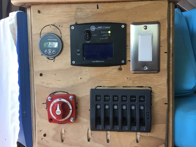
How to Plan an Electrical Control Panel
Note: this post is a series on the electrical system. Please view the previous post here to get caught up.
I've got the battery pack installed. I've got my inverter/charger installed to keep the batteries charged, and I have the inverter capable of powering a wall outlet off battery power alone. Most skoolies would direct the inverter to go to an AC control panel, with circuit breakers and grounding bars and all those things you'd find in one of those grey boxes on the side of your house that say "WARNING - SHOCK HAZARD". But since I don't really have any big AC requirements (it's literally just one outlet to power a laptop charger, and another outlet that powers the air conditioner), I'm relying on the protections built in to the inverter itself. The AIMS inverter has a built in 30 amp circuit breaker that will trip if an AC load is drawing more than 30 amps. If I had an AC control panel, I'd have to put all the different circuit breakers there for each AC circuit. Like I said, I only have one AC circuit, so the one built in circuit breaker is sufficient.
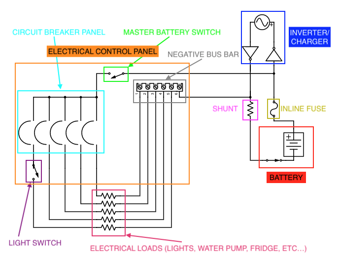
But that's not the case with DC. Let's follow the flow of current leaving the positive anode of the battery. It first encounters a 30 amp inline fuse, which serves as whole bus protection. If any DC load (or AC load for that matter) pulls more than 30 amps at one time, the fuse will break and thus protect the whole electrical system. The other side of this fuse is connected to the inverter/charger (so that anything on the other side of the inverter is also protected by this 30 amp fuse), and it also runs to the electrical control panel. It's about six feet away from the E-Bay, so the cables need to be sized appropriately (6 AWG in my case). This cable runs from the inline fuse through six feet of 6 AWG cable to the input bolt of the master battery switch.
Why have a master battery switch at all? Why not just connect this six-foot-long 6 AWG cable directly to the light switch, or water pump, or refrigerator? Well, the obvious answer is safety. If the water pump develops a short, drawing more and more amps, eventually the 30 amp inline fuse will break and cut power off to the entire bus, even though it was only the water pump that malfunctioned. So we need to protect each DC component with its own circuit breaker or fuse, and that way you isolate the electrical system which isn't only safer, it's more convenient because if there is a malfunction, you'll know what component it is. You will also still be able to charge your phone, run your fridge, and use your lights if it's just the water pump.
I prefer circuit breakers over fuses for a few reasons. One, it acts as an on/off switch. Turn the circuit breaker on, and it applies power and will automatically turn off if there's a short. Two, you can reset the circuit breaker if you've decided the problem has been fixed. Circuit breakers use heat as a tripping mechanism--as more and more current flows through a wire, it will start to heat up, which is why wires and cables need to be the appropriate size, otherwise they'll melt and cause all sorts of hazards. Imagine that inside the circuit breaker, the wire is designed to only heat up to a certain amperage/current: they're rated for amps, not volts, and once the amps exceeds a certain threshold (i.e. once the wire heats up to a certain temperature), the circuit breaker flips and cuts off the circuit. If you flip the circuit breaker back on immediately, the wire will still be hot and thus it will flip itself back off. If you keep resetting a circuit breaker like this, eventually you'll melt through the wire and now the circuit breaker is busted. That's why it's important to wait a while before resetting a circuit breaker--the wire must cool off otherwise it'll just trip again. (Again, don't take this as literal truth--this is just a mental model to help me understand how they work).
Back in my sailboat days, I nearly caused an electrical fire by constantly resetting a circuit breaker powering my space heater. Eventually it stopped working, even if I reset it, and once I pulled the panel off to take a look, I saw the actual wire going into the circuit breaker had burned itself off, and the surrounding rubber jacket/sheath was covered in scorch marks. That was a valuable lesson that day: if the circuit breaker trips more than once, even after you think you fixed the problem, just call it a day and investigate the whole circuit. Don't keep resetting it thinking it'll "just work."
Fuses have one major advantage over circuit breakers, however--they're cheap and plentiful. Most cars have a fuse box and you can buy automotive fuses pretty much everywhere. It's a good idea to have a box of spares on hand, especially in a Skoolie, for when old components burn through and short. For example, I have that 30 amp inline fuse protecting the battery. Why not have a 30 amp circuit breaker? I suppose I could, but it seems that higher amp circuit breakers start to get really expensive, while fuses remain pretty cheap. But another reason is that if this inline fuse breaks, it means there is a serious electrical malfunction somewhere in Argo's electrical system. If it blows the fuse first thing out of the battery, I sure as **** won't be turning anything back on. I'm not going to reset that circuit breaker because it means that I need to inspect everything, which won't be happening on the trip.
So that's my strategy: fuses for higher amp "master" protection, and circuit breakers for individual components. So now I know I'll have a circuit breaker panel, but why have a master battery switch if the circuit breakers act as an on/off switch?
I suppose it's not necessary. But it's convenient to have a switch that will turn off all DC loads, but leave the inverter/charger connected and running. It also turns off the indicator lights in the circuit breakers, thus saving some juice. If you have more than one battery bank, it allows you to switch between them or connect them both, which is useful for isolating loads or having an emergency backup battery.
Anyway, back to the flow. The current leaves the battery, passes through the inline fuse, enters the master battery switch, and if the switch is on, leaves the switch and goes directly into the input of the circuit breaker panel. I generally leave most things off if I'm not using them.
Let's say I want to turn the lights on. I first turn the master battery switch on, which now powers the circuit breaker panel (it also illuminates the labels for each circuit breaker). I then flip the "Cabin Lights" circuit breaker, which now allows electricity to flow from the circuit breaker panel to the light switch. I then flip the light switch, which then allows current to flow from the light switch, through the long wires behind the ceiling shiplap, and into the lights. So now the lights are on, and the current now enters the negative side of the circuit. It leaves the lights, flowing through the black wire that runs back through the ceiling shiplap and back to the electrical control panel. But it doesn't go back to the light switch; that switch is simply for the positive side of the circuit. Instead, it returns to the negative distribution block, or bus bar.

Every circuit's negative wire comes back to this bus bar. It's fine that they're all "touching" like this, because all the switches and protections are on the positive side of the circuit. The circuit breakers, fuses, switches--that's only for the positive side. The negative side can all come together like this no problem. In fact, for most busses' electrical system for the lights and radio and stop signs, they use the bus's chassis as the negative bus bar. The whole metal frame of the bus becomes part of the negative circuit. You can use this same strategy for some of your circuits too, by having, say, a negative bus bar in the kitchen, where all the kitchen items (fridge, fans, lights, etc...) have their negative wires come to this bus bar, and then a single cable that goes from the kitchen back to the negative bus bar in the electrical control panel. If you do this, however, make sure you size this combined cable appropriately for all the components' current.
This negative bus bar then has a 6 AWG cable that runs behind the seats (along with the original 6 AWG inline fuse cable from above) back to the E-Bay. There, it's attached to a shunt, which provides battery monitoring capability. The shunt measures how much current is flowing through itself, and if you input the battery's capacity in amps, it will tell you how many you have left (similar to how my flow sensor tells me how much water I have left). This post of the shunt is also connected to the negative terminal on the inverter/charger. The other side of the shunt is connected to the negative terminal of the battery.
So that's the flow of electricity in my system, and it illustrates the role of the electrical control panel for not just safety but also convenience. The control head for the battery monitor/shunt is up there, along with the control head for the inverter/charger, meaning I can monitor and control my entire electrical system from that single panel up in the front.
Where to Locate the Electrical Control Panel
This is really up to convenience. The closer it is to the battery bank, the safer and cheaper it will be (long, large cables are expensive). But for me, I really want to be able to open the bus door, maybe take one step, and be able to turn the lights on from there (the nights can get pretty dark up in the mountains). So I have the electrical control panel position immediately to the left of the bus door, contained within the forward bulkhead of the guest bench.
It's also important to put it in a location where it will be convenient to access the backside of the panel for when things inevitably go wrong. There also needs to be enough space for the wires, not just for normal operations, but for when you are removing the panel--the wires need to be long enough to support you taking the cover off without disconnecting anything. You also don't want a wire to work itself loose and cause a short. Finally, good wire organization is sexy, and requires enough room to space them out.
For me, I made the bulkhead a few inches deep, such that the backside of the control panel would have a few inches of room for all the wires. Yes, this shortened the length of the bench a bit (and thus makes it more difficult for tall people to sleep there) but there really isn't any other way around it. Especially when I have such a short bus.
How to Install the Electrical Control Panel
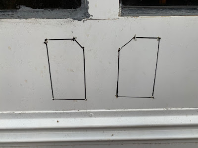
This one is also up to you. I used 3/4" plywood for the bulkhead enclosure, and for the front facing panel, I used a router and jigsaw to cut openings big enough to hold the five components of my electrical control panel: the battery monitor, the inverter/charger controller, the light switch, the master battery switch, and the circuit breaker panel. You may have to use the router to make certain parts of it thinner to accommodate smaller switches, but I didn't need to with mine.
It goes without saying that you should not have any electricity on the bus when doing this. This is why I put a master battery switch cutoff on the battery itself--that way I know no electricity is in the circuit because it's cut off at the source. I also ensure the inverter/charger isn't plugged in to shore power.
Since we're on a school bus that rumbles down the road, it's important to plan on all the vibrations. This will ever so slightly damage weak connections, or wiggle nuts loose over time. That's why it is critical to use proper crimp connectors and heat shrink all the joints. For bolt connections, use a locking washer. Finally, it's important to carefully ops test each circuit to make sure it's installed correctly before you button everything back up.
That's pretty much it. Most of this is going to be up to the user to decide, but it's important to have the conceptual layout of the electrical system down before installing anything.
Common Gotchas
- Make sure your wiring/cables are appropriately sized for the maximum amount of possible current. See my previous posts for determining the right cable size
- The location is a balance between convenience and safety/money--the closer it is to the battery bank, the safer and cheaper it will be--but it may not be convenient, depending on how much space is available
- The backside of the panel needs the right amount of room to contain all the wires. If you pull the panel out, make sure the wires are long enough to stay connected to everything as you work on it and replace it
|
|
|
|
|
05-12-2020, 08:07 AM
|
#153
|
|
Bus Nut
Join Date: Apr 2018
Posts: 421
|
How to Install a Refrigerator in a Skoolie
How to Install a Refrigerator in a Skoolie
You've got your floors, walls, everything built. Your electrical system is installed and works. I opted to build the kitchenette from the floor up, and that meant I had to install the diesel heater and fridge before framing out the drawers and putting the sink in. This was really the last part of the build that basically got "whatever's leftover," from a sizing perspective. Meaning I had a hard requirement for the bed size (Queen), which meant that the dinette seating on the left side of the bus (the kitchen side) extends approximately 60" forward from the back wall. So that's where the bulkhead goes that marks the aft end of the kitchen. On the forward side, I have a bathroom immediately aft of the driver's seat. I built a wall as close to the headrest as possible, then made the bathroom as small as it could be, accounting for a large person like me sitting on a toilet. This involved planning the toilet to face at an angle within the bathroom to maximize lateral space for my shoulders. After I installed the aft wall for the bathroom, that left a small open space for the kitchen.
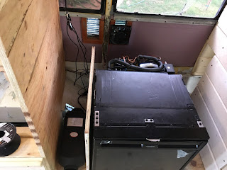
To further shrink this, I put a diesel heater between the wheel well and the center aisle (see photos), since I figured that would be dead space anyway given the wheel well's shape. So now that further shrinks the available area to put a fridge by bumping up another bulkhead frame. On the front end, I have the sink drain going down into the holding tank, so obviously I can't have a fridge that extends further forward than that. This left approximately ~24" for the maximum width of my fridge.
What about vertically? Well, I knew I wanted to have the counter located at the same level as the middle of the window, such that I could open the window once the counter is installed. I also knew the sink I wanted, which has extraordinarily large dimensions since it will double as a baby bathtub (and crib at night!). With the sink 10" deep from the middle of the window, I knew the upper limit of the fridge height. And the depth is only limited by the back wall and the inner edge of the kitchen drawers.
So I started looking for 24V refrigerators with a width of less than 2 feet, and settled on the Dometic CRX-65 refrigerator, designed with truckers in mind. It fit perfectly in the space available, with a few inches to spare in every dimension.
Given its location, however, I knew there wouldn't be much airflow for the compressor in the back. These things can get pretty hot, and can absolutely overheat and cause RV/boat fires. At the very least, I needed a simple vent to allow hot air to escape outside the bus. I knew this far in advance, but I didn't actually know exactly where the fridge would go, so I cut a vent into the wall that would allow one fan to suck exterior air in and another to blow interior air out. In hindsight, this is kind of overkill, because a single fan blowing hot air out would've been much more efficient and quieter than having two fans. To space these fans apart, I put the vent across a rib to make sure I wasn't recycling air and also so I would only need one exterior vent cover. Knowing what I know now, I wish I would've just waited to cut the vent until I knew exactly where the fridge would go, and only put one fan blowing air out in a much more efficient design. This is one of many mistakes/learning opportunities on this skoolie.


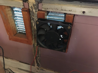
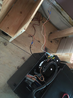
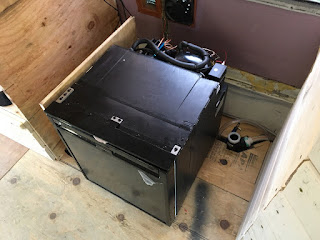
Anyway, once I got the vent cut in and ready to go, and the location of the fridge determined, I put the fans and fridge in place. For power, the fridge runs on its own circuit, and I preran cables through a PVC pipe under the floor in anticipation of installing 3 electrical components on the opposite side as the batteries. Since I put the floor in so long ago, before I really knew exactly where things would go (same as with the vent), this conduit actually comes out of the floor underneath the fridge. Fortunately for me, the CRX-65 comes with a defroster drain, such that if you defrost the fridge and the accumulated ice melts, it drains out the bottom. The fridge has little legs tall enough to accommodate this 10mm tubing, tall enough to allow the wires to exit the conduit freely.
Using spade crimp connectors, I plugged in the fridge, turned it on, and made sure everything worked. Using a voltmeter, I measured the voltage of the compressor fan (even though the fridge is a 24V model, the compressor fan runs at 12V). I then unplugged from power, unplugged the wires that power the vent fan, and spliced two new wires coming from this 12V power supply going to the fridge's compressor fan.
Anytime the compressor fan is getting power (as in, any time the compressor is running), it also triggers/powers a 12V relay that then closes the vent fan circuit. The vent fan circuit is powered directly from the 24V spade crimp connectors that the fridge also receives power from. I'm sure I'm making this more complicated than it needs to be, so to recap: the 24V power supply that comes through the conduit in the floor (and controlled with the refrigerator circuit breaker) is connected to two things: the fridge, and the vent fans. The positive wire for the vent fans, however, goes through a 12V relay, which is triggered anytime the fridge compressor fan runs. It then runs to an on-off switch on the bulkhead (along with a USB charger and the diesel heater control head) so I can turn the fans off in cool weather when they're not necessary. The positive wire then finally runs to both fans, turning them both on, blowing hot air out, and then the negative goes directly back to the conduit in the floor.
The refrigerator also receives power from the conduit. However, the circuit board of the refrigerator has a label, which clearly shows which wires are the positive and negative for the compressor fan. Since these wires would only receive power if the compressor is running (the only time the fan turns on), I spliced an additional wire to both the positive and negative that run to the relay mentioned in the previous paragraph. If you're new to relays, all this does is connect the fan positive wires together if there's electricity flowing through the relay; if there's no electricity going through the relay (as in, the compressor is off) the positive wires for the fan circuit are disconnected.

 Common Gotchas
- The compressor needs to be ventilated! Don't just stick it against a wall with nowhere for the hot air to go. But also don't do what I did with two fans and a weirdly shaped vent--a single fan will do. Also the fans I got are probably too big and loud
- Sizing the fridge correctly. For me, it was basically whatever was leftover from my other requirements. Which means it's a lot smaller than I wanted, but that's just how it goes--don't get a fridge that's too large, otherwise it won't fit and will drain your batteries
- Get a fridge with a built in drain, otherwise risk water damage from defrosting when it leaks out the door. My friends don't have a drain on their fridge, and thus they simply leave it running 24/7 on their van powered by solar
|
|
|
|
|
05-14-2020, 08:52 AM
|
#154
|
|
Bus Nut
Join Date: Dec 2017
Location: Sandpoint, ID
Posts: 542
Year: 2003
Coachwork: Girardin Microbird MB-IV
Chassis: Ford E450
Engine: 7.3 Diesel
Rated Cap: 25
|
Argobus,
Thanks for all of your detailed, and thoughtfully written posts!
|
|
|
|
|
05-15-2020, 03:02 PM
|
#155
|
|
Bus Crazy
Join Date: Apr 2019
Location: SW USA
Posts: 2,064
Year: 2003
Coachwork: IC / Amtran
Chassis: CE300
Engine: International T444e
Rated Cap: 23
|
Quote:
Originally Posted by peakbus
Argobus,
Thanks for all of your detailed, and thoughtfully written posts!
|
I just came to say exactly the same thing. Just starting to digest this build and there's SO MUCH detail. Excellent thread. So much to learn! 
__________________
Go away. 'Baitin.
Our Build: Mr. Beefy
|
|
|
|
|
05-15-2020, 08:29 PM
|
#156
|
|
Bus Nut
Join Date: Apr 2018
Posts: 421
|
Thank you sirs for the kind words. Im having a lot of fun not just doing the conversion but writing about it too.
|
|
|
|
|
05-15-2020, 09:45 PM
|
#157
|
|
Bus Geek
Join Date: Sep 2015
Posts: 3,856
Year: 2002
Coachwork: Thomas Built Bus
Chassis: Freightliner FS65
Engine: Caterpillar 3126E Diesel
Rated Cap: 71 Passenger- 30,000 lbs.
|
Your enjoyment of the writing process shows in that which you write.
|
|
|
|
|
05-17-2020, 11:43 AM
|
#158
|
|
Bus Nut
Join Date: Apr 2018
Posts: 421
|
How to Vent a Battery Electrical Compartment

Why Vent the Battery Compartment?
Note: this post is a series on the electrical system. Please view the previous post here to get caught up.
Most batteries need to be vented, which really just means they need to be in a secure compartment that gets fresh air. Lead-acid batteries slowly release hydrogen, which is fine unless there's no ventilation, allowing the hydrogen to build up around the batteries. It doesn't take much of a spark to ignite hydrogen. Even AGM batteries, which are simply lead-acid batteries that don't need water refilling, still have to be vented. Nickel-cadmium batteries are completely sealed, and although they still release gas, it remains in the cell and is recombined. Lithium batteries, in my opinion, are the superior type of battery (also the most expensive!), as they do not vent either. But just because the battery itself doesn't off-gas anything doesn't mean that they should be in a sealed compartment.
Since I have lithium batteries, I'll just be using them as an example. As any battery generates current, it will heat up. This is similar to why higher current wires (such as those that charge the batteries) have to be larger and thicker--high amounts of current generate heat. In general, batteries work best at a reasonable temperature. At cold and hot extremes, the batteries are less efficient. For lithium batteries, there's actually a specified range for both charging and discharging.
- Charging Range: 32°F to 113°F
- Discharging Range: –4°F to 140°F
If you'd be spending some time in colder climates (why would anyone purposefully drive their skoolie to freezing weather? Just drive it somewhere warmer!), then the batteries would actually need to be heated above -4F to use. And if you use them, and need to charge them, then they need to be warmed to above freezing. Putting them in the cabin could solve this problem, so long as it's heated. But for me, I don't see myself spending any time with Argo in below freezing climates. So I'm not concerned about the lower threshold here, I'm concerned about the high temperatures.
Temperatures in California routinely exceed 100F. Put a big metal bus in the sun, with little insulation and full of windows, and the temperature inside the cabin will exceed that of the ambient air outside. But if I'm in the cabin, surely I'd be taking steps to cool it down. I'd open windows and even turn on the air conditioner. But the air conditioner is powered by the batteries through the inverter, which is also in the E-Bay. That process of inverted DC power to AC power generates significant heat. Never mind the fact that the batteries generate heat on their own.
The point is, it isn't so much about batteries off-gassing, it's about keeping them and the other electrical components cool. How to Vent the Battery Compartment
My battery compartment (or E-Bay) contains all my battery pack, a shunt/fuse, and the inverter/charger. The biggest concern will be the inverter/charger, as that will generate much more heat at normal use than the batteries will. Normally, inverter/chargers must be installed with a certain clearance to allow for this ventilation. The manual for mine says I need 12" of clearance to allow sufficient airflow. It also has an internal vent fan, which follows this schedule:

In non-engineer terms, it basically says the internal fan will turn on in three different scenarios:
- Temperature: if the internal temperature exceeds 149F, the fan will turn on. It won't turn off until the temperature dips back below 140F.
- Charging current: if it's charge current is greater than 20% of its max, the fan will turn on (for my model, the charge current is 30 amps--so if the batteries are depleted enough where it's pushing out 6 or more amps, the fan will be on). It won't turn off until the charging current dips back below 15%, or 4.5 amps.
- Inverter load: if the inverter is being used at at least 30% capacity, the fan will turn on (for my 2000W model, that means if I'm pulling 600W of AC power from my outlet, it will turn on). It won't turn off until the inverter load dips back below 20%, or 400W.
As I've alluded to before, the only real AC load I'll have is the air conditioner, which I've already ops tested to pull 475W. So the inverter load doesn't really apply here. I've also scaled back the charging current to 25% of its normal maximum, to allow the balancers to balance more efficiently as it charges. Sure, it'll take longer, but when I'm plugged into shore power, that generally means I'm home and not going anywhere. So my max charging current is 7.5 amps, meaning the fan will turn on if the batteries are pretty much depleted.
That leaves the temperature as the main factor driving the vent fan in my situation. And since the inverter/charger is stuffed in the E-Bay alongside the batteries, there really isn't any natural ventilation. Combined with normal usage, and the ambient temperature, it'll get quite hot in there, which will further degrade the battery/inverter, which will cause it to get even more warmer, which will cause it to further degrade... it's a positive feedback loop that needs an external break.
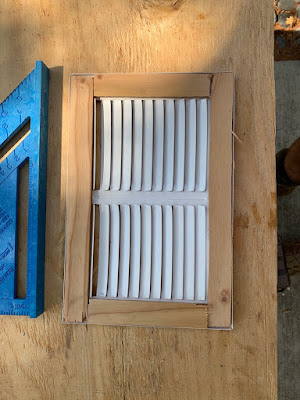
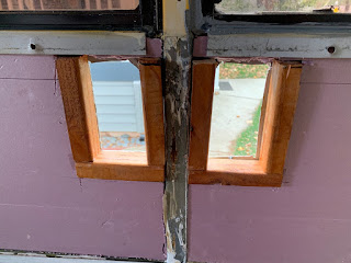
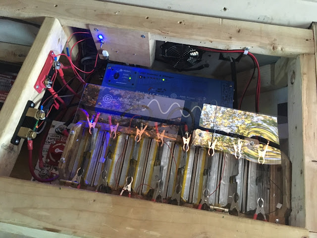
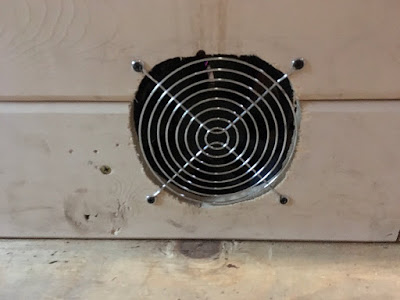
Thus I put two fans in there: one pulls air in from the lowest part of the cabin (where the coldest air will be), and the other pushes hot air outside the bus. This required careful planning to allow adequate airflow from the fans to the inverter/charger, as that's the primary component that needs cooling. See the image below:
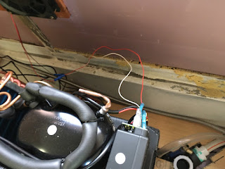
The inverter/charger is along the wall, so it's close to the 30 amp RV inlet (see this post here for more on that). Its fan is located on the DC side (the left side of the photo), which sucks air in and blows it through the inside, where it leaves on the AC side (the right side of the photo). So I installed the intake fan (that sucks cooler air in from the cabin) on the left side of the E-Bay, which also required me to make a sort of "wind tunnel" through the battery's control panel. Here's the "wind tunnel":

That allows cooler cabin air to flow around the battery box, where it will meet the DC portion of the inverter/charger, where it will meet the inverter/charger's internal fan. That fan will blow through the inside of the inverter/charger, taking some heat away with it, and exit through the ventilation grille on the AC side of the inverter/charger. There, it will be pulled out of the bus by the exhaust fan.
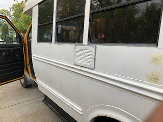
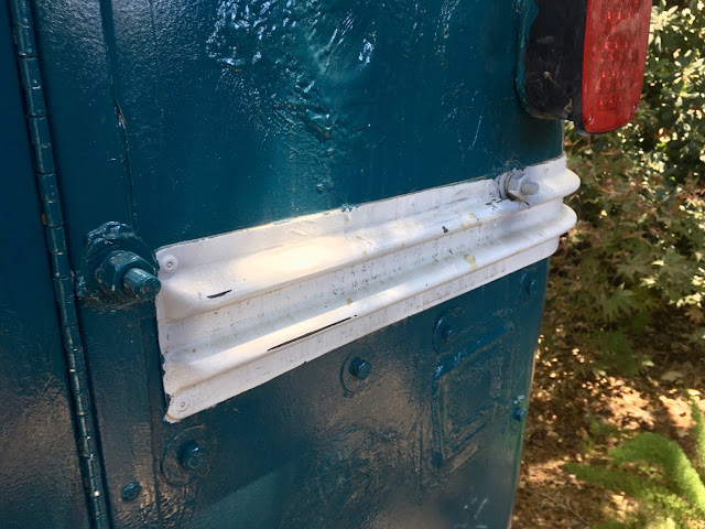
As far is installation goes, this simply requires cutting a circular inlet inside the cabin, so that the fan can suck in as much air as it can, and then cutting another circular exhaust on the outside wall of the bus where the exhaust fan can push the hot air out. This outlet also needs to be protected from the elements, so that rain and splashing roadwater don't come up into the E-Bay. Water and electronics don't mix well. So I installed a fresh air intake cap to keep the water out.
I chose this style of vent cover, as opposed to the vent grille style cover I used for my refrigerator's vent fan, because it's in a little more "austere" of a location. The wall for the fridge's vent fan is simply a single layer of sheetmetal, as it's higher up on the wall and actually angled slightly away from the road (and protected by the cool school bus trim). The E-Bay exhaust fan, however, is much lower on the wall, and thus closer to the road, and is actually angled downward, meaning splashing road water actually has a chance of making it up that high. It also goes through the skirt of the bus, meaning there's an inch between the exterior wall and the interior wall where the fan is. This inch of space needs to be protected, because if splashing water got up and in there, it would trickle down and cause all sorts of mayhem inside the skirt. It also has a built-in screen to keep bugs out.
Here's a few more views that show the fan installed on the skirt, and the 30 amp RV inlet with its triplex wires (also the under floor electrical conduit).
Okay so maybe I didn't do so good with the circular cut.


So that's how the vent fans are installed, but there's one last point here before moving on: how big should the fans be? Well, this one was easy for me, because the inverter/charger manual states:
Quote:
|
Do not expose the Inverter to rain, snow, spray, bilge or dust. To reduce risk of hazard, do not cover or obstruct the ventilation openings. Do not install the Inverter in a zero-clearance compartment. Overheating may result. Allow at least 12” of clearance around the inverter for air flow. Make sure that the air can circulate freely around the unit. A minimum air flow of 145CFM is required.
|
I know I'm violating the 12" clearance rule, so I'm using these fans to make up for it. How much air do they need to push? At least 145 cubic feet per minute. So I hopped on Amazon and looked for 24V fans that have a flow of at least 145CFM, and found some that actually push 152CFM. I figure if I have a fan pushing 152CFM in, and another one pulled 152CFM out, then I'll be good.
It's important to note that this was originally inspired by SomewhereinUSA's project here (https://www.skoolie.net/forums/f49/l...ion-29559.html).
We could very easily just put an on-off switch on some panel somewhere, and when "it's hot out" just turn the fans on. But that's so sloppy and inefficient, and most of all, I'm too lazy to be bothered with that. So I figured out a way to automatically turn the fans on when the E-Bay air temperature exceeds a certain threshold.
The Arduino Nano is the smallest most basic Arduino computer available. It does three different things in this installation: it turns on an LED when it's working properly, it senses the air temperature, and it triggers a relay if the temperature exceeds 99F. If the Arduino is powered up, but can't sense the temperature for whatever reason, then the LED will blink. If the LED is off, then the Arduino is also off, and automatic vent operation isn't on. That's it. It's super simple.
Let's run through the wiring in order to explain what's going on. Here's an overview:

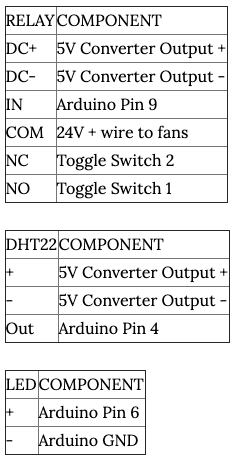
The 30 amp inline fuse of the electrical system (see my previous post for more info) has a small wire which powers this vent fan circuit. However, since this circuit comes before the DC control panel and its circuit breaker protection, I need to put a small fuse here to protect in case there's short. So the 30 amp inline fuse has an 18 AWG wire that then connects to a 7 amp fuse, which then goes to the 3 position toggle switch. This provides power for the Arduino and fans.
Let's say we want to turn the fans on, regardless of the temperature. We'd flip the switch to position 2, which now receives 24V power from the switch's INPUT, and goes directly to the NC, or Normally Closed, input of the relay. The relay itself isn't powered at all; thus, the COM, or Common, output is always connected to the NC input. So now the 24V power comes into the NC and out of the COM, which goes directly to the fans' + wires. The fans turn on, and their - wires go to the 24V - input of the 5V Converter. This 5V converter has nothing coming in to the 24+ side, so it isn't powered on. But that's fine, we're just using it to connect the - wires. So the fans' - wire goes to the 24V- input of the converter, which also has another wire that goes to the 24- shunt of the electrical system, thus completing the circuit. The fans are on and running, protected by the 7 amp fuse, and I can leave them running as long as I have battery power.
Let's say we want to have the fans in automatic mode. We'd flip the switch to position 1, which now receives 24V power from the switch's INPUT, and goes through two different wires. One wire (again, this is 24V) goes to the NO, or Normally Open, input of the relay. This means that in normal circumstances, the NO isn't connected to anything, and won't be until it receives a trigger signal to the IN input. The other wire leaving the toggle switch position 1 goes to the 24V + input of the converter. Since the 24 - input of the converter is always connected to the negative shunt of the electrical system, the converter now has power and converts the 24V electricity to 5V.
The 5V output powers the Arduino, the DHT22 temperature sensor, and the relay. I could've had the DHT22 and the relay powered by the Arduino no problem, but the Arduino only has one power output pin, and it doesn't really matter anyway since all components simply need 5V power, regardless if it comes from the converter or the Arduino.
The DHT22 temperature sensor is now powered up, and sends the temperature data to the Arduino.
The Arduino, now powered up, does a few things. It turns on the LED to indicate the script is running. If it isn't receiving good temperature data from the DHT, the LED blinks. If it is receiving good data, the LED is a solid color. That way I can know if I need to troubleshoot or turn on the fans manually, lest I risk overheating the compartment.
If the Arduino receives good temperature data, and it's below 99F, it does nothing. If the temperature exceeds 99F, it sends the trigger signal to the relay and pauses for five minutes before checking the temperature again.
The relay, now powered up, simply awaits the trigger signal from the Arduino. When it receives that, it flips the relay to the NO position, now connecting the NO input to the COM output. Remember, the NO is receiving 24V power from switch position1, thus it will push out 24V power out the COM line so long as the Arduino sends the trigger signal. The COM line goes directly to the fans' + wires, powers the fans, then returns to the 24V - input on the converter, and finally back to the shunt, thus completing the circuit.
Here's the code:
[Due to character limitations, I can't put the code here. But it is available on github here (https://github.com/TheArgobus/ebay_f...r/EBAYFANS.ino) or at the build blog post here (https://theargobus.blogspot.com/2020...t-battery.html)]
This isn't pretty and it's not the most effective/efficient way to code, but since this Arduino is only doing a single task (read temperature; trigger relay), the delay() functions work just fine. To recap: it turns the LED on, and reads the temperature. If it fails to read the temperature, the LED blinks. If it reads the temperature, the LED stays solidly lit, and it repeats this script every second. If the temperature exceeds 99F, it sends the trigger signal to the relay (digitalWrite(relayPin, HIGH);) and waits five minutes before rerunning the script (delay(60000)). If the temperature is still high, it keeps the relay triggered and waits another five minutes; if the temperature is normal, it turns the relay off, thus turning the fans off.
How did I determine 99F/37C is considered hot enough to trigger the fans? After all, the ambient temps around California often exceed 99F. I used this academic paper, published in Electrochemistry Communications in 2005, as a reference. Here's what the abstract says (emphasis added):
Quote:
|
The high-temperature storage and cycling characteristics of prismatic Li-ion cells with carbon-coated LiFePO4 cathodes, MCMB graphite anodes and a LiPF6/EC–DEC electrolyte were investigated. The cells showed a significant capacity fade when cycled at 37 and 55 °C. Li–Sn reference electrode studies indicated that the interfacial impedance of the graphite electrode increased significantly during high-temperature cycling. Carbon-coated LiFePO4 electrodes were found to release iron ions into the electrolyte when aged at these temperatures; EDAX analyses confirmed the presence of iron at the surface of the graphite electrodes. The observed impedance rise of the graphite electrodes and the consequent capacity fade of the cells were attributed to the formation of interfacial films that were produced on the graphite electrodes as a result of possible catalytic effects of the metallic iron particles. The cycling stability of the cells was improved significantly when the LiPF6 electrolyte salt was replaced with the lithium bis-oxalatoborate LiB(C2O4)2 salt.
|
So basically, I decided that since this paper shows "significant capacity fade" starting at 37C/99F, why not have the fans turn on at the temperature to start cooling them down? If I used the temp data from the inverter/charger, I'd have the fans turn on at 140F, but at that point the batteries will be hella hot and would have already started to degrade. Not to mention that it takes time to cool things down, and you want to start before it gets too hot. So I decided that 37C/99F is the ideal temperature to start cooling LiFePo4 cells.
To install this whole thing, I just put all the components on a piece of scrap wood, and drilled it in place at about the same level as the batteries. Since it's inside the E-Bay, it doesn't really matter how polished it looks, it just matters how well it works.
And it does work. I tested it by changing the threshold temperature to a degree above ambient, then exhaled on the temp sensor, and the fans turned on. Five minutes later, they turned off. So I just leave the switch in position 1 (automatic), which turns the LED light on, and now if the bus is sitting in my driveway, and if it ever gets too hot, it'll vent itself! No action from me necessary.

Common Gotchas
- Not venting your electrical/battery compartment. Even if you have totally sealed batteries, it's still a good idea to vent to keep temperature down.
- If able, position your inverter/charger in such a way that it has plenty of air ciriculation on its own. Since I have a shortie, space is limited, so I had to create this improvised way of ventilation
- Size your fans correctly! Look in the manual to see the minimum cubic feet per minute (CFM) required, and get fans that meet or exceed that requirement.
|
|
|
|
|
05-17-2020, 01:59 PM
|
#159
|
|
Bus Geek
Join Date: Jan 2019
Location: Philadelphia
Posts: 7,000
Year: 2003
Coachwork: International
Chassis: CE 300
Engine: DT466e
Rated Cap: 65C-43A
|
These are great posts, man. Thanks for going to the trouble and effort.
|
|
|
|
|
06-07-2020, 02:36 PM
|
#160
|
|
Bus Nut
Join Date: Apr 2018
Posts: 421
|

We took Argo out on our first official trip; three days, two nights, with electricity and plumbing and cushions installed. There's a little known reservoir in the Sierra Nevadas that's really hard to get to but totally worth the journey. They have pull in camp/RV sites with fire pits, pit toilets, but no hookups of any type. That was fine, because I budgeted my battery bank for 3 days on a full charge, but we had a new, unplanned electrical load: an electric bassinet called a Snoo. Fortunately, it worked out just fine, but there were a lot of interesting observations here:
- The only way to recharge my batteries at this point is with shore power. I have a 3.6kW LiFePo4 bank, which was plenty for our trip without recharging
- It was over 100F in Northern California the day we left. While plugged in to shore power in my driveway, I turned the AC on to try and cool the bus down while we loaded everything. At this point, I am unable to run the AC without shore power, at least until I get the solar panels installed. I could turn it on but it would kill the batteries in a few hours and probably overheat the inverter long before that happened, so it's effectively inop unless we're plugged in. So we opened the windows and it was still hot as balls in back. The infant was quite happy with the warmth, however, and she slept the entire way
- When I installed the seatbelts, I was sure to install a car seat LATCH system in the back. I used 1/2" eye bolts through one of the ribs and I'm really glad I included it, because the car seat works like a champ! Because of the spacing, the seat is super secure and doesn't move at all, and since there's no slope like in a car, it actually leans back a little bit which is more comfortable for the baby, who slept the entire 2 hour drive

 - Part of the route to get there took us down and up a super steep valley on a single lane road. As we neared the bottom of the valley, which itself is an amazing park/campground, I started smelling an acrid burning stink, which I thought was coming from the electrical compartment. The fridge was running nonstop, since it was so hot out, and maybe my wiring was faulty or perhaps it was getting too hot in there and my cooling system wasn't working. I thought it was more likely to be part of the bus itself, though, so when we got to the bottom I pulled over and inspected the brakes. Sure enough, the front left brake was SMOKING real good. The bus was fully loaded--36 gallons of water, two adults, one kid, one infant, and enough food/supplies for all of us--and it looked like I had loaded it too unevenly toward the front axle. I have quite a bit of professional experience with hot brakes, and knew that it would take at least twenty minutes to let them cool off. Fortunately, the next part of the journey would be going uphill, meaning we wouldn't use the brakes very much, so after we chilled for thirty minutes, feeding the baby and checking everything over, we took off and it worked great. Once I got home, I got an appointment scheduled to change all the brakes, and will be loading the bus next time with as many heavy things in the back as possible (we didn't do that this time).
- Once we got to the site, we got settled in. I realized that my propane stove leaked gas when plugged in, probably because I was using the wrong adapter (it came with a thin metal rod that I left home; I believe this is actually necessary now). Without a propane stovetop now, we were limited to the fire pit, which had a spinning grate attached. Fortunately, we also packed a cast iron dutch oven type thing, which came in handy for cooking the bacon.
- Storage is obviously an issue in a shortie, and we realized we overpacked by about 33%. We had way more food than we needed, way more gear (why did we pack a tent and a cot?), too much of pretty much everything. We don't really have the cabinets installed yet, so we just threw everything in the bathroom (which is just a closet at the moment). Lesson learned: pack less than we think.
- The electric bassinet, called a Snoo, runs off 120V. I tested it out before we left and it pulled less than 100W when running, but it has variable speeds depending on how much the baby is fussing. Fortunately for us, it fit perfectly over the sink (which is the baby's bed anyway) and saved us many hours of sleep that first night. However, this unplanned electrical draw really took a lot of the battery's capacity, since it essentially runs nonstop throughout the night, which leads me to the next point:
- I seriously underestimated how much electricity we used. When I was planning this out, I used the documentation for all our devices to budget our electricity. I had planned the refrigerator to use 400W over 24 hours, which ended up being far less than reality. I knew the compressor would run for a bit, then turn off, then run for a bit... but during the day time at ~100F, it ran non stop for hours. And hours. After 48 hours from unplugging from shore power, the batteries had reduced to 50% capacity according to my battery monitor. But when the fridge was running, it said I had 2-3 hours of runtime remaining. Meaning if we stayed for another day, the fridge would kill the batteries by noon, since it needed to run nonstop during the hot day time. So realistically, I have 48 hours of runtime with the bus, during hot weather and including an electric crib. Once the baby gets old enough and won't need it, that will probably go back up to 72 hours, and of course if it's cooler out, we won't need to run the fridge as much. But this, combined with the super hot temps while driving, really means I need to:
- Install the solar panels. We took the bus out on a day trip to the lake, where it was parked in full sunlight for a few hours. This would've topped up the batteries I'm sure, since they would be recharging during the drive up there and partially at the campsite. Not only that, we need to get the AC running, but that has it's own issues since I installed it on the front side of the bus where the airflow will be opposite of the fan (whoops). This is now the priority for my next project.
- We also need to paint the interior and get that settled. All of us ended up with some splinters in our hands.
- The water counter was super awesome, especially when washing dishes. We only used maybe 10 gallons of water while we were there over 48 hours. I like that kind of usage.
- The water heater is installed, but not hooked up. We quickly discovered that if we had the faucet using cold and hot water, pressurized water would shoot out of the hot water input of the faucet. That was a fun cleanup.
- And of course, we got some great photos too.

All in all, it was a great first trip, and everyone had a great time. We shook it down and figured out what's important and what's not, and will definitely be taking it out again soon. It feels SO GOOD to finally use it successfully after working on it for two years! It's all worth it now, and I encourage everyone reading this to just hang in there and you'll find all the blood sweat and tears will pay off!
|
|
|
|
|
|
 Posting Rules
|
You may not post new threads
You may not post replies
You may not post attachments
You may not edit your posts
HTML code is Off
|
|
|
|
 » Recent Threads
 |
|
|
|
|
|
|
|
|
|
|
|
|
|
|
|
|
|
|
|
|
|
|
|
|
|
|
|
|
|
|
|
|
|
|
|
|
|


 Linear Mode

