|
|
 08-18-2019, 07:19 PM
|
#61
|
|
Bus Nut
Join Date: Jan 2019
Posts: 375
Year: 2003
Chassis: Chevy cut-away 6-window shortie
Engine: 6.0L Gasser
|
I've used fiberglass on a number of spots on the bus, and agree it does a good job filling holes. To help get some of them started, I ran packing tape behind the holes and started fiberglassing against that. The holes from my flashers were filled that way!
Chris
|

|

|
|
08-20-2019, 10:42 PM
|
#62
|
|
Bus Nut
Join Date: Apr 2018
Posts: 421
|
How to replace all the Skoolie lights with LEDs
Whelp, I got pulled over for having multiple lights out. Apparently, there's quite a few regulations I was busting.
What Lights Does a Skoolie Need?
Check out this page. For vehicles wider than 2032mm or 80 inches or 6' 8", you must have a suite of identifying lights (for vehicles longer than 30 feet, there's additional lights, but I won't go into that here since I have a shortie). Long story short, a vehicle wider than 80 inches needs:
On the front end, in amber:
- Three lights at the highest point, centered and six inches apart
- A light at each side of the roof
- Reflector tape near the bumper on both sides
On the aft end, in red:
- Three lights at the highest point, centered and six inches apart
- A light at each side of the roof
- Reflector tape near the bumper on both sides
- Tail lights
- Turn Signals
- Brake lights (including the 3rd brake light, centered and at a higher level)
We're going to focus on the marker or running lights (called "clearance" and "identification" lamps on that page) first.
How to Replace Skoolie Running Lights
First, we need to remove the old shitty lights. Inside the bus, clip the wires going to all these lights so that they can be removed on the outside. Some of them may only have one wire leading to them, as the ground can be through the chassis.
Remove the screws and pull the lights off. Some of the screws were too corroded or stripped to work, so I simply ripped them out or used a grinder to remove them. This will leave holes and tears in the body, which is fine as we'll patch them next.
How to Patch Holes in the Skoolie Body
See my previous post for a more detailed write up. Mix up your epoxy, and apply the fiberglass as necessary. It's okay if it looks rough--we're going to sand it down and all the blemishes will look better once the bus is painted. Let it cure for at least a few hours before proceeding.
How to Install New LED Lights
The button LED lights I linked to are great, because you only need to drill a 3/4" hole to fit them. They're water-proof, and the included rubber seal certainly will resist water, but I decided to line the grommet with silicone sealant as well just to make sure.
Once you drill the hole, insert the light carefully. This may take a few tries, as it is a snug fit, but that's what we want. Oh, and it may be a good idea to strip a little extra off the end of the pigtail wires just to make it easier for the next step.
For these lights, the white wire is the ground, and the black wire is the positive end. That's kind of annoying. To complete the install, simply crimp the black wire to whatever wire you clipped earlier, and then connect the white wire to the ground (sometimes it's a wire, but usually it's just to the chassis). Turn your headlights on to see if you've done it correctly. If they work, hooray--if not, get out your voltmeter and double check your attached the correct wires where they need to go. LEDs have polarity, so it has to be correct.
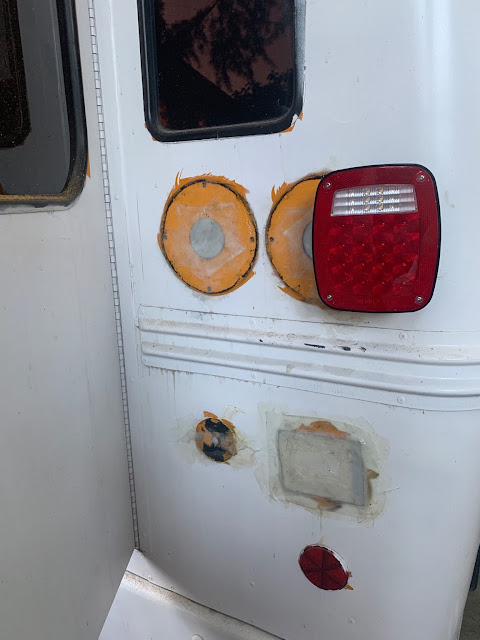
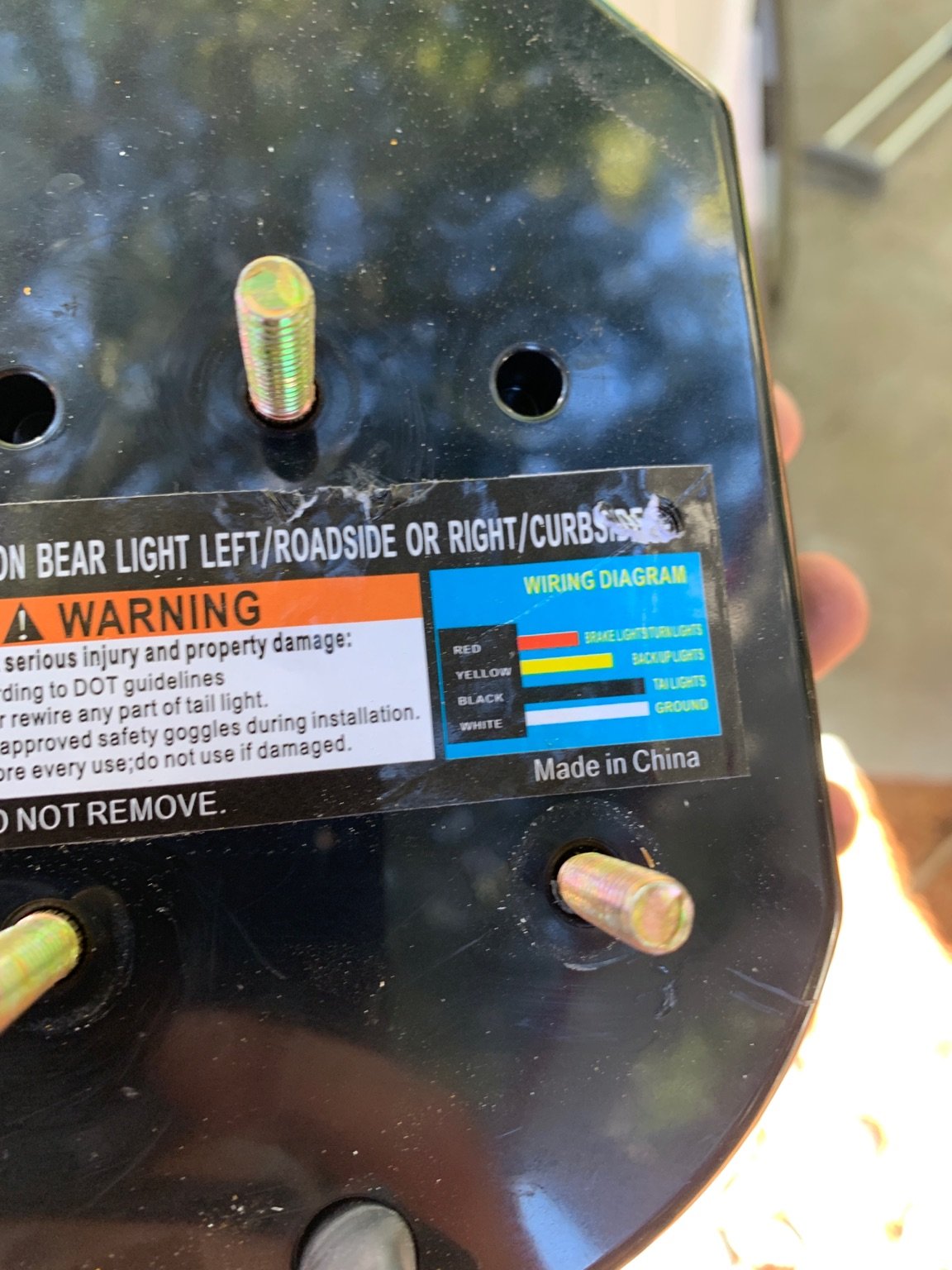
How to Install New LED Brake Tail Reverse Turn Lights
Now we're getting more complicated. This is going to be different for every bus--for mine, the tail lights came on along with the brake lights, so I had to determine which wire going to the tail light was associated with turning the headlights on, and associated with pressing the brake light. I tried using a voltmeter, but found it was a lot easier to just loosely attach an extra LED button light from above to see which one came on. Once I identified the tail light wire, I labeled it and clipped it.
I then labeled all the other wires (turn signals, reverse light, brake light) before clipping them as well. Trust me, labeling before cutting is the most important step.
With the wires cut, I then unscrewed and removed the lights on the outside. I didn't care about being neat for this step, since I patched the ensuing holes with metal plates as outlined in my previous post (using fiberglass as well).
So now that the entire aft end of the bus was free and clear of lights, and patched over with fiberglass, I could install the new LED light fixtures. I went with the same vertical position, but spaced a little further out (also to fit my license plate lateral to one of the lights). The lights I linked to have a handy little guide for the wiring which makes it easy to wire them up.
I mounted them by drilling three holes for the bolts, and one for the wiring pigtails. I used some silicone sealant around the screws to make sure they were waterproof. Then I wrenched the lights into place on the inside, tightening the including nuts on the bolts.
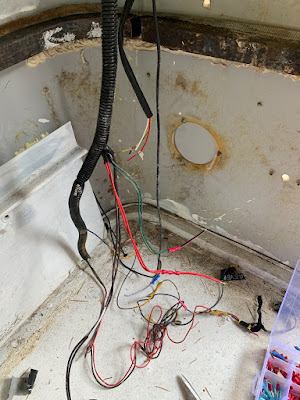
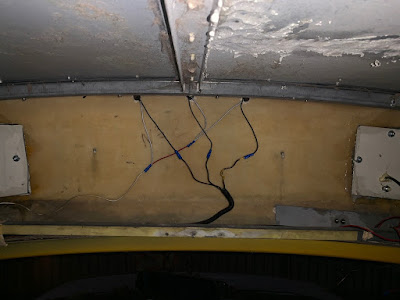
There was a lot of extra wiring that I removed. One needs to be careful here to make sure they remember which wires are which (please label them). The brake light is straight forward. So is the tail light, and the reverse light. Once you attach the ground, it should be up and running. Test it by turning the headlights on, shifting to reverse, and braking--but ensure that you haven't left any bare wires hanging around, because if they contact the chassis, they could spark.
It's worth mentioning here that you must add a wire from the brake light wire to the third brake light bar. I installed mine above the door, and the one I linked to also includes a low light mode for the headlights, which I then wired to the running lights on top of the bus.
About the turn signal lights. One cannot have both the turn signal and the brake lights wired to the same fixture, as if you brake with the turn light on, the brakes will keep the light on, thus removing your turn signal. Not cool. So we have to install a separate light for the turn signal.
This step is basically identical to the main LED light fixture, with one big difference--the hot wire for the turn signal also needs to be attached to the chassis ground through a 50W 6ohm resistor. This is because the relay for the turn signal is expecting a bulky incadescent bulb, and if you simply replace it with an LED one, it'll "hyper flash" or flash rapidly, and possibly burn out the relay. Thus we need to simulate an incandescent bulb using this resistor.
The turn signal wire must go to the new LED turn signal, as well as the resistor, which then connects to the chassis. Just an FYI, this resistor gets HOT, so make sure it's installed away from other wires or potentially flammable material. Then the LED turn signal has a ground wire that you must also attach to the chassis.
Once everything is installed, it is essential to test everything in each configuration (for instance, brakes with both headlights on and off, in reverse, etc...). It's also important to make sure you have the necessary reflector tapes installed where they need to be (reference the linked page in paragraph one).
The last step is to install the license plate lights if necessary. This one should be pretty easy by now, as you simply splice the tail light wire and lead it to the license plate light, and then ground it on the chassis too.
Common Gotchas
- Label everything before you cut. I cannot emphasize this enough
- Make sure the power is off when you work; I forgot this once and was promptly reminded when I cut through two wires
- Test everything before you go out on the road in each configuration--this will probably be a two person job
|
|
|
|
|
08-21-2019, 09:41 PM
|
#63
|
|
Bus Nut
Join Date: Dec 2018
Location: Mt Vernon, WA
Posts: 523
Year: 1996
Coachwork: Bluebird, Collins
Chassis: G30 Bluebird Microbird, E350 Shuttle Bus
Engine: 1995 Chevrolet 350, 1992 Ford 460
|
Thanks for the detailed thread. And that reminds me about a resistor in the turn signal circuit. Id forgotten about that.
Ive had a couple of those Ford short buses and a newer one with the 6.0 L diesel. I liked the older ones like yours. Now I have a 1995 Chevy short bus not converted yet. Empty still, no seats. I think Im about done trying out vehicles and hold on to it.
Its so interesting to read other build threads and see how its done.
A note for other builders :Ive managed to remove the seats in all the buses by myself without air tools. Only needed to clamp vice grips on a few bolts underneath to keep them from turning. Going under and spraying the nuts with PB Blaster first helps. A angle grinder with a cut-off wheel removes the ones that are stuck hard. Usually only one or two except for on the rusty bus I got back East. Lucky here in a Washington State with so little rust.
Look forward to more forward progress.
|
|
|
|
|
08-22-2019, 11:23 AM
|
#64
|
|
Bus Nut
Join Date: Apr 2018
Posts: 421
|
Quote:
Originally Posted by Doktari

Ive managed to remove the seats in all the buses by myself without air tools.
|
Well done. This was the worst part about the demolition phase, maybe second to ripping up the floor. Doing those parts alone were hard enough with a partner, but as I'm starting to realize with most things for this conversion, everything takes three times as long to complete.
For the LED light replacements, as an example, it took me three full eight-hour days to finish, and even then one of the tail lights didn't work, so I had to troubleshoot an additional few hours later in the week.
That's all right, though, I would much rather take the time to do it right the first time--especially for safety equipment like the lights. And to prevent water from seeping in through the holes.
|
|
|
|
|
08-22-2019, 02:41 PM
|
#65
|
|
Bus Nut
Join Date: Dec 2018
Location: Mt Vernon, WA
Posts: 523
Year: 1996
Coachwork: Bluebird, Collins
Chassis: G30 Bluebird Microbird, E350 Shuttle Bus
Engine: 1995 Chevrolet 350, 1992 Ford 460
|
Good work!! Good lighting is very worthwhile. That phase in on my list.
As we dont do this everyday it takes way way longer than someone all setup with a shop, tools, and experience.
Im learning how to work with aluminum; collected a bunch of 1 square tubing, sheet aluminum, angle, channel, and bought collection of rivets at an estate sale. My new cordless rivet gun arrived yesterday. Drilling lots of holes is the challenging part as I have elbow pain.
I hope to make racks, solar rack, gas tank holder, etc.
|
|
|
|
|
08-24-2019, 08:31 PM
|
#66
|
|
Bus Nut
Join Date: Apr 2018
Posts: 421
|
Quote:
Originally Posted by Doktari
Good work!! Good lighting is very worthwhile. That phase in on my list.
As we dont do this everyday it takes way way longer than someone all setup with a shop, tools, and experience.
Im learning how to work with aluminum; collected a bunch of 1 square tubing, sheet aluminum, angle, channel, and bought collection of rivets at an estate sale. My new cordless rivet gun arrived yesterday. Drilling lots of holes is the challenging part as I have elbow pain.
I hope to make racks, solar rack, gas tank holder, etc.
|
Right on. Rivets are definitely the strongest, there's a reason why aircraft are riveted instead of welded or bolted.
|
|
|
|
|
08-31-2019, 08:40 PM
|
#67
|
|
Bus Nut
Join Date: Apr 2018
Posts: 421
|
Well I tried to remove the windows to reseal them, as a few of them leaked... and I could only remove one window. That's it. Conveniently, that's the one that leaked the most, but the others wouldn't budge, even after removing the screws and applying a heat gun to loosen up the seal. So, instead of straight up fiber glassing over all the seals, which I was about to do out of rage, I just used som Autotron 550 Seam Sealer to slather over the existing seal, and guess what? It stopped leaking. I did remove the sealant around the one window I could remove, and resealed that using even more seam sealer, and we're all good now. But holy hell, I didn't expect removing the windows to be such a bitch.
|
|
|
|
|
08-31-2019, 09:40 PM
|
#68
|
|
Bus Nut
Join Date: Dec 2018
Location: Mt Vernon, WA
Posts: 523
Year: 1996
Coachwork: Bluebird, Collins
Chassis: G30 Bluebird Microbird, E350 Shuttle Bus
Engine: 1995 Chevrolet 350, 1992 Ford 460
|
Thanks for the heads up for autotron seam sealer. Im going to check it out as my shorty seams are getting questionable. A wet moldy difficult to dry sub-flooring was the result in my previous short bus. The original windows can leak. That may be one reason so many builders replace them.
The seam that attaches the coach to the van roof is starting to fall away. Ive been wondering what to use.
One product thats good also is trim and seal adhesive. I think 3M makes it and its super useful and sticky for getting trim and seals back in place. Its commonly available to.
|
|
|
|
|
09-29-2019, 09:15 PM
|
#69
|
|
Bus Nut
Join Date: Apr 2018
Posts: 421
|
How to Install a Water Pump on a Skoolie
Make sure you get the same diameter size for all items. 1/2" diameter seems to be the standard size for RV water pumps and fittings
Where to put a Water Pump on a Skoolie
Since I have a short bus, space comes at a premium. I don't want to have the pump under the sink, because I want that space for food or other storage that's easily accessible from the kitchen. I also want to keep the amount of "head" or distance the water has to travel upward prior to getting sucked into the pump) at a minimum, so I wanted to keep it near the same level as my water tanks (see my previous post).
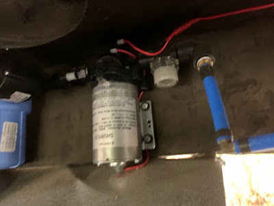
The general flow is this: water travels from the bottom of the tank, through PEX lines (I went with PEX because it keeps the plastic taste down and can withstand heat), to the strainer (to prevent debris from entering the pump), to the water pump, to the accumulator (this prevents the pump from running when you are using the water for only a few seconds like, say, when you're brushing your teeth), to the water filter (this one is strictly for drinking purposes), and then through PEX lines to my sink and fixtures. Simple, right?
Well, it turns out I can fit all those things under the stairs on Argo. This is why I put the fresh water tank on the same side as the stairs.
How to Mount a Water Pump on a Skoolie
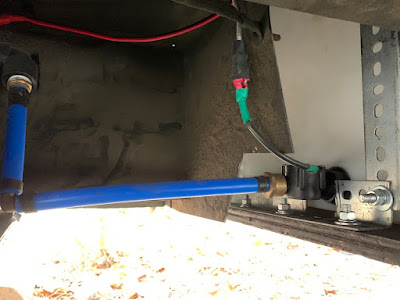
This is when pictures work better than words. I used some of the PEX - NPT Fittings to be able to attach a PEX line to the outflow port of my water tank, and then I had use two 90 degree fittings to lead the PEX line back up to where the inlet is of the water pump (see the pictures) (ignore the wired inline attachment... that's a flow sensor for a future project). I attached the strainer and the accumulator directly to the water pump, and then mounted all those to the wall of the stairs. I then used a bit of PEX line to go from the accumulator to the filter, because the filter needs to be far enough away where you can easily unscrew the housing to replace the filter itself.
This isn't the prettiest job--it left a few bolt heads exposed on the stairs, but I'll be covering those up at a later date. This also leads to the issue of the pump hardware being exposed to the road. Rocks can fly up, dirt dust and grit will accumulate. I didn't need anything structural down there because the stairs were supporting the hardware, but I needed something protective to keep things from flying up into the pumps. Fortuantely, I saved all the sheet metal from the demolition phase, so I used a grinder to cut a piece and mounted it underneath all the hardware. I then sculpted it to fit appropriately, and secured everything in place using additional bolts.+
A side note here: I believe I used regular zinc plated bolts from Home Depot. I should've used galvanized to prevent corrosion. Whoops.
But now how do we get the water from under the stairs to the sinks and fixtures?
How to Plumb a Water Pump on a Skoolie
My fresh water tank is on the starboard size; my grey tank is on the port. I chose this specifically because I wanted to put the pump et. al. under the stairs, and I wanted the sink to drain straight down into the tank (I don't want to deal with clogged pipes running across the bus).
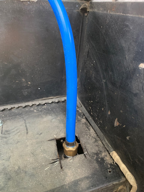
So to run my PEX line across the bus to the opposite side, I had two options. I could run it underneath, which would require me to shield it with some cast iron pipe or PVC or something like that to protect the line from debris and the axle and whatnot. Or I could run it up into the bus, and then across going through the floor. As in, running under the wood floor, but above the metal base, such that it runs through the insulation. This is what I opted for, and I'm sneaking ahead now because I haven't done the write up for the subfloor.
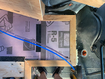
I used 1" insulation directly on the metal, with 3/4" plywood on top, as my floor (laminate to be added post painting). I cut a hole in the stairs directly above the output of the filter, such that I could connect a PEX line to the filter, and then curve this PEX line through the floor to the opposite side of the bus where the sink is planned to be. I simply attached a whole lot of PEX to the filter, and then ran it to where I think it would go, bending it as necessary, and cutting it to length. This ended up with a solid elliptical curve, as I wanted to keep hard joints to a minimum (they reduce water pressure). With the insulation already on the floor, I marked out where the PEX line would be, then used a router to cut a neat line through the insulation that could fit the PEX line.
The insulation is 1" thick. The PEX line is 1/2" thick. This means that the PEX line still has 1/2" insulation protecting it from the metal floor, which is good because it runs right across the exhaust/transmission area and that spot gets quite warm. Once I made the cut through the insulation, I stuck the PEX line in (which was already crimped to the filter) and put the ply wood down, thus sealing the pipe in.
At the end where the sink goes, I put an elbow fitting to go from under the floor to straight up, then a few inches later put a Tee fitting so as to send the cold water up to the sink, and send some of the water to a future water heater. But that's for another post.
Common Gotchas
- Make sure all your items have the same diameter. I had to return multiple items because I accidentally bought 1/4" instead of 1/2" (this goes for 12V vs 24V too)
- Use Teflon Tape for all fittings, to really make sure there's no leaking--you don't want to have any leak downstream of the pump (How do you use it properly? )
- You may notice that these things can start adding up quickly. You don't have to use PEX, you can use vinyl tubing with hose clamps for much cheaper, but you're also going to have to tighten them constantly because of how much busses vibrate going down the road, and how much vinyl flexes with the heat, and nevermind the taste of vinyl. So in my opinion, just pony up the money and do it right the first time. That's why we're converting a school bus in the first place, right? To get a level of luxury that you can't find in cookie cutter RVs? At least that's how I feel about it.
|
|
|
|
|
10-13-2019, 10:04 PM
|
#70
|
|
Bus Nut
Join Date: Apr 2018
Posts: 421
|
How to Install a Skylight in a Skoolie
Well I'm feeling pretty clever. I installed a skylight, of which the materials cost $70. There's prettier and better ways to install one, especially one that's premade, but I wasn't sure they would fit. So here it is.
Where to Install a Skylight on a Skoolie
I had a few restraints when installing the skylight. Some were aesthetic, others were functional, and it just so happened they all worked out.
- Above the master bed for seeing the blue sky upon waking up (or the stars while laying down)
- Positioned in such a way that it wouldn't hinder future solar panel installations (for instance, a skylight in the middle of the roof wouldn't work too well)
- Also positioned in such a way that it wouldn't require any cutting of the ribs
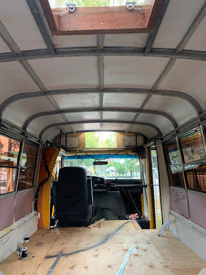
Fortunately, there was a location that met all three requirements--at the aft end of the bus (where the bed will be), there was a strange gap centered on the ceiling where the bus frame went around an open "square" of fiberglass. Probably meant for an emergency hatch, but now it was going to be my skylight.
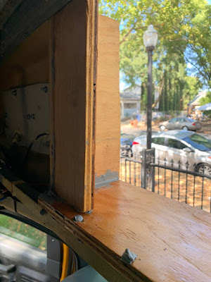
How to Build a Skylight for a Skoolie
The general idea is illustrated above. You have a vertical surface that lines in the inside of the opening, which extends up past the roof in order to prevent water from coming in, while also having a lip that doesn't extend as far up in order to secure this vertical surface to the roof. Then, the lid has a lip as well that extends downward and fits on the lip of the vertical surface, therefore ensure that water has no way to get in.
The first step is to measure how big the skylight will be. I know what solar panels I want, and how many, so I essentially measured how far back on the bus the solar panels would go, and added a quarter of an inch for slop, and then decided that was how far forward the skylight could go. Then, I found the aft most rib and determined that was how far aft the sky light could go. The further aft, the better, since that's where the bed would be.
Fortunately, the piece of plexiglass was sized such that it would fit in this window (between the aft rib and the last solar panel) with a few inches to spare, so I wouldn't have to resize the acrylic panel and decided that it would be the final size of the skylight. (But that's not how big to cut the hole).
Essentially, given the crude diagram above, I knew I'd have to take the width of the plexiglass, minus the width of the lumber for the lip, and the width of the lumber for the vertical surface (on both ends), to obtain the proper dimensions, so I started cutting the wood into the components. Once cut, I put three coats of polyurethane on to really seal it in and keep it long-lasting, and then assembled the components. Keep in mind, I had to guess how deep the vertical surface would have to go in order to pass through the roof and the as-yet-to-be-installed ceiling.
Also, I made the bottom edge of the "lip" slightly angled to compensate for the roof's curve. As in, the outer edgers were maybe 1/2" to 3/4" deeper than the middle of the lip.

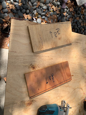
The "lip"

Upside down view of the skylight with the "lip" installed.
Note how I put copious amounts of seam sealer in all the joints. I really really really don't want water leaking in through the roof and causing mayhem with the build.
I saved the thin edge that I cut off from the lip to use as the lip for the acrylic panel lid, since it would fit nicely where it was cut from. I also made sure that this thin wedge of wood would fit snugly on the lip, and be flush with the top, such that the acrylic panel would lay flat on everything. It will make more sense soon.
Using the self tapping screws (I should've drilled pilot holes through the acrylic, because it cracked a litte), AND copious amounts of seam sealer, I attached the thin leftovers of wood from the vertical surface's lip to the acrylic panel so that they would form the acrylic panel lid's lip. Once this was build, all I had to do was attach it using the piano hinge.
But now how do we keep it from swinging all the way open, and keep it "within reach" when you want to close it? I couldn't find any levered arms or hydraulic pistons, so I just used storm door springs. After some trial and error, I found the sweet spot to place them such that they would keep it open far enough where it would be out of view when looking out, but not so far that we couldn't reach it when we wanted to close it.
Finally, the last step was to figure out a way to keep it locked closed such that the wind when driving wouldn't make it fly open. I'm sure there are many ways to do this, and many better ways, but I just used what was on hand. I picked up two locking safety latches and two u-bolts. I attached the u-bolts to the acrylic, and then basically closed it and eyeballed the correct position for the latches. (See photos above).
Now the skylight is fully built and functional, it's time to install it.
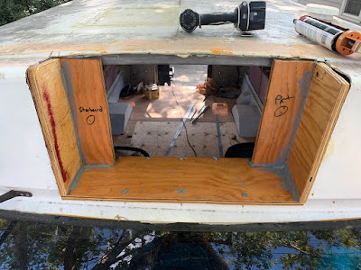
How to Install a Skylight on a Skoolie
Inside the bus, I drilled pilot holes marking where the opening would be (essentially, it was the size of the rectangle of the vertical surface that would slide through the roof). I hefted the skylight up to the roof, lined it up such that it was centered on the pilot holes, and traced it with a marker. Then, using the grinder, I cut it out. It took a few tries to fit the skylight in--there were a few rough edges that needed further grinding, and it eventually slid into place, with the outer lip keeping it from falling through.
Now I pulled it back out, and using like an entire tube of seam sealer, lined the bottom edge of the lip with a ton of it. Then I put it back in and pushed it down, making sure some of the seam sealer squeezed out, which confirmed it was enough. But it really wasn't.
Next I used construction screws and drilled down into the lip from above and through the roof. This essentially squeezed the roof and the skylight together, removing any empty space and filling whatever remained with seam sealer. It also became clear that I may have applied too much, as a lot of it squeezed out the edges, which I then smoothed over with a rag.
And that's pretty much it! It rained after a day or two, and there were no leaks, so now I have a functioning skylight in precisely the right dimensions and location for my particular bus and bed location--all for $70.
Common Gotchas
- I should've drilled pilot holes when drilling through the acrylic. I also should've just "hand-tightened" the u-bolts, because I tightened one too much and cracked it.
- Use seam sealer everywhere. Future you will appreciate it.
- The placement is key--if you plan on roof racks or solar panels, make sure you plan appropriately, and avoid cutting through any of the ribs, which impacts safety and structural integrity.
|
|
|
|
|
10-23-2019, 12:21 PM
|
#71
|
|
Bus Nut
Join Date: Apr 2018
Posts: 421
|
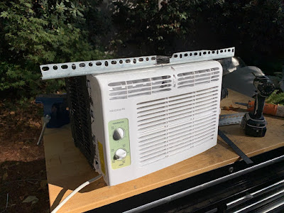
How to Install a Window Air Conditioner in a Skoolie
Man, I've been knocking out a bunch of big projects, and I'm only now getting around to documenting them. I've got my first kid on the way, so I now I have a hard due date to finish this conversion (I hear you don't have a whole lot of free time after your child is born). Anyway, here's my take on how to install a window air conditioner in a bus.
https://theargobus.blogspot.com/2019...nditioner.html
How to Choose the Right Sized Window Air Conditioner for a Skoolie
Here's a great source for sizing your air conditioner, reproduced below.
- Square Feet to be cooled: BTU rating
- 0-150: 5000
- 150-200: 6000
- 200-250: 7000
- 250-300: 8000
- 300-350: 10,000
- 350-400: 12,000
- 400-450: 14,000
- 450-500: 15,000
The astute mathematician will see there's a simple formula here. To obtain how many BTUs you need, simply take your square footage and multiply that by 30. But that's for a stationary room that isn't rolling over hot pavement with a massive engine below the floor. So, as a general rule, I add 30% to account for extra heating. In my case, Argo is approximately 100 square feet, giving me a BTU rating of 3000, plus the extra 30%, leading me to an ideal BTU rating of 3,900. Lucky for me, there smallest air conditioner I could find was 5000 BTUs, so it'll be even better than what I planned for.
How to Power a Window Air Conditioner in a Skoolie
inspired me to go down this route. The particular model of Air Conditioner he used (as well as I) is a 5000 BTU model, which also has a slow start up to save power (the start up is the biggest electrical draw). It uses 450 watts of power, and as a rule of thumb I always add 30% when trying to figure out electrical load, so my assumption is that at max blast, this thing will draw 585 watts. Now, my battery bank (as yet to be installed) contains 3600 watts of LiFePo4 electricity, and my charging capability is in three 300 watt solar panels. If, when driving in the sun, I'm getting 70% efficiency from the solar panels, then I'll be pulling in 630 watts, which is just over the max blast draw from the air conditioner. Give the inverter a 30% efficiency drop, and now my solar panels would be pushing out 441 watts at 120V. This means that, worst case scenario (with the AC drawing more power than it should, solar panels and inverter running at 70% efficiency), I'll be losing about 144 watts per hour. This shouldn't be a problem with my 3600 watts of battery bank. But still, this is at a worst case scenario. But that's a future me problem.
Where to Install a Window Air Conditioner in a Skoolie
Argo doesn't have any dash air. No air conditioning, no heating, no nothing. So this will primarily be running when I'm driving during the summer months, but I also want to be able to run it without moving, meaning that it needs to have plenty of circulation around the back end of the unit. I'll spare you the details, but air conditioners need air circulation to work. Window units in your home are great because there's plenty of clearance around windows, and the manuals dictate just how much clearance you need. I can't remember what this one called for, but it was something like 12" all around, but I knew I could go less than this because it would primarily be used while driving, so that it would always have constant air flow going around.
The other big thing is that I didn't want it to go in an actual window because, in my opinion, it looks tacky (funny because the end result also looks tacky, but I like it more).
I also wanted it to go as high as possible, because cold air sinks and having an air conditioner on the floor would drive me crazy due to the stratification of cold and hot air (my feet would be freezing, and my head would be sweating).
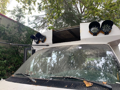
Finally, from an aesthetic point of view, I wanted it mounted on the bus centerline, which left only two possibilities: either at the aft end of the bus, or the front end. And the aft end was already taken up with a skylight, so the front end of the bus it was.
Note that the clearance lights will have to get removed and reinstalled somehow.
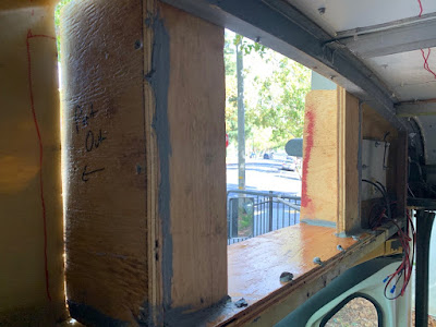
How to Install a Window Air Conditioner in a Skoolie
Fortunately, I had a rib that ran along the ceiling here, and in line with it, approximately 13" inches below, was a straight cross beam. This meant that, with a 3/4" plywood base, I'd have 1/4" clearance to work with. The plan was to use the ceiling rib as the "window" against which the air conditioner would lean against, but this also meant that it would be extending out the front of the bus by a significant amount. That's okay, because this also meant that when I am stationary, the air circulation will be okay.
The first step was to basically create and install a "frame" that the air conditioner would fit into. This frame would also prevent water (either rain or drainage) from entering the bus, and provide a little structural support to hold the air conditioner up. It also needed to give the air conditioner a slight tilt downward on the outside for drainage.
How does one create this frame? Mainly by trial and error. I first determined how wide it was going to be. Remember the exterior clearance for the air conditioner? Well I'm obviously not going to cut out a 3 foot wide hole, and this is okay because remember I'll be driving, and when I'm not, most of the air conditioner will be extended out of the bus anyway. Still, a portion of it would be contained within this "frame." So I figured I'd take a quarter of the width of the air conditioner, and use that for the lateral clearance. The clearance on top wasn't an issue, because it would just be exposed to the air. And you don't necessarily need clearance on the bottom, except for water draining. So the hole I plotted out to cut was approximately 2 feet wide, and I removed to the roof here as well (all the way back to the ceiling rib). And for the bottom, I used a level to measure approximately where the bottom spar lined up with the outer skin. See the pictures for more details.
I used 3/4" plywood for this purpose, and since it was going to be exposed to the elements, I gave it 3 coats of polyurethane sealer for protection.
I first started with the bottom board, which would span the whole length of the opening. Once I measured about how big it'd be, I cut it and stuck it in place, where I realized I hadn't cut the hole properly to allow a low enough tilt. So I busted out the grinder, and ground down the bottom edge of the opening by another quarter inch. Then I put the board back in, measured it with the level to make sure it had enough tilt, and repeated until it was definitely tilted enough to allow drainage.
Once it was good, I screwed it down into the bottom spar that crossed directly underneath the ceiling rib. Remember, I had already sealed this piece of wood with three coats of polyurethane. But I noticed it was still level, as it was only screwed to the spar on one end; the front end was free floating and basically level. So I screwed it down into the bus exterior, which wasn't a pretty job as the ends of the screws came out the other side, but this will be fine because I'll fiberglass over them later.
Next, I created the side boards with essentially the same method. I measured approximately how big they'd have to be, then cut the boards to fit, remembering that there would be a 3/4" panel at the aft end of the base board (which would replace the accordion style panels provided with the AC). I labeled them appropriately, because the port and starboard sides were slightly different. Oops. I put them in place and, using a permanent marker, marked out the curvature of the bus' exterior skin. Then I cut them to fit using a jigsaw so that there wouldn't be any hard corners sticking out, and it'd be nice and smooth. Again... once they fit, I made sure they had three coats of polyurethane.
Once they were dry, I put them back in and lined the seams with a good amount of seam sealer. Then I screwed them into the base board from the bottom up. The other side (on the outside) would be fiberglassed to the body, so I wasn't worried about securing that just yet.
The last part of the frame was the side panels, which would replace the accordion style ones provided with the air conditioner. These were pretty easy to cut to fit, as they had square edges, with the exception of the top, because the roof curves slightly. Once I cut them and they fit, I sealed them and again, used copious amounts of seam sealer before screwing them to the base board and the side boards. Now the "frame" was essentially built, and the last step was to seal it with fiberglass and epoxy.
The final step for the frame is the fiberglass. This was how I was going to ensure it'd be waterproof, particularly along the seams, and this would also protect the wood and give it a significant amount of structural support.
My preferred method for fiberglassing is as follows. Using the provided hand pumps, mix together three pumps of resin and three pumps of hardener; mix thoroughly for one minute, then add colloidal silica, mixing as you do, until it achieves the consistency of pancake batter. Then, using a foam brush, apply some of this epoxy mix to the surface, followed by a strip of fiberglass cloth, and then apply more epoxy until it's thoroughly coated.
I may have went overboard with the fiberglass, as I coated every seam with two coats (including two pieces of cloth), and then I also coated the flat surfaces of the wood with at least two coats of epoxy and one cloth. I really don't want water leaking in here. By the time I was done, I essentially made this frame an integral part of the bus's exterior skin.
 Note the plastic protection over the windshield... I didn't want any epoxy dripping down
While the fiberglass was curing, I went ahead and painted the exterior of the air conditioner black to help it blend it better with the future shielding I had planned.
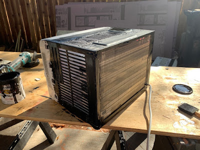
I used an extra piece of angle instead of the provided hardware to catch on the ceiling rib (see photo above) using the self tapping screws linked to above, but it is very important to make sure those screws will not be puncturing anything. There's quite a bit of electronics and tanks and pipes under the skin.
Next I hefted it up and tried to slide it into place and quickly realized I had to shorten the slotted angle because the ceiling rib curves downward. So I removed the air conditioner, grinded the metal shorter, and repeated this process probably five times. There were metal divets leftover from when I removed the ceiling that I had to grind down, and then finally it fit!
Until the metal legs on the front edge caught on the base board. Although I had 1/4" of clearance in the center, because the ceiling rib curved downward toward the side, I actually was now 1/4" too long on the edges. Fortunately, this problem was solved by grinding off the little feet. Unfortunately, I got a little too aggressive and punctured a tube, and got a face full of refrigerant.
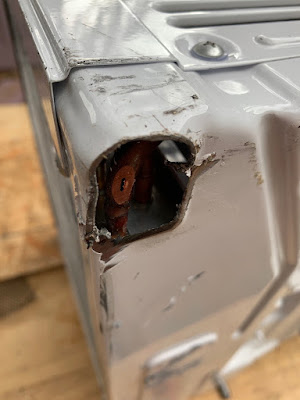
Fantastic. I destroyed the air conditioner. Thanks to Amazon, two days later, I had a brand new air conditioner, just like the one I lost. I painted it again, and installed the slotted angle, and carefully removed the feet with the grinder. In hindsight, I also could've just used a router to cut some divets into the base board, but it was already fiberglass in and it's not perfect.
Anyway... now it fit. It still required a few fine cuts on the slotted angle to make it fit with the correct back angle, but once it did, I rejoiced.
I set the air conditioner to the side to work on the next phase, which was created a "cage" with which to conceal the air conditioner and protect it from flying debris. Using more slotted angle, I made the first four arms slightly longer than the air conditioner itself, such that it would extend beyond the a/c by about an inch or so. I then through bolted these arms to the wooden frame (using seam sealer at the holes) and installed them so they'd be sticking out on their own. Next, I lined the inner side of these arms with the black mesh grille and bolted that to the arms as well (for both sides and the bottom--I held off on the top because that was my only access at the moment). See the photos for more.
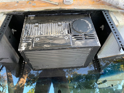
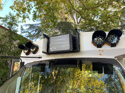
Note I also had already painted the angle black with the same paint as the A/C. Next, I repeated this process for the front grille--measure, cut, paint, install, bolt the grille on, admire.
At this point, I new I could install the A/C, since I no longer needed to access the inside of the "cage". I inserted the A/C, verified it had the correct angle, and then used the self tapping screws to screw the slotted angle to the ceiling rib.
I gave it a few good shakes and this thing is solid and sturdy. It ain't moving unless we get rear ended and it flies toward the back of the bus, hitting everyone sitting in the back. Since safety is at the top of my mind, I realized I needed to give this thing a cleverly named safety strap. I measured out a good length, bolted one end of the slotted flat bar to the side board, then ran it across the front of the a/c, and marked a good hole on the opposite side board. I then through bolted it to this new one and now we have a super secure air conditioner.
But what about waterproofing the gaps between the a/c and the box? Well, I happened to have some extra insulation laying around (1" thick pink board), so I cut a few thin slices, shoved them in the gaps, and sealed them with seam sealer. In hindsight, I should've just used the provided foam strips that came with the air conditioner, but whatever.
|
|
|
|
|
10-23-2019, 12:24 PM
|
#72
|
|
Bus Nut
Join Date: Apr 2018
Posts: 421
|
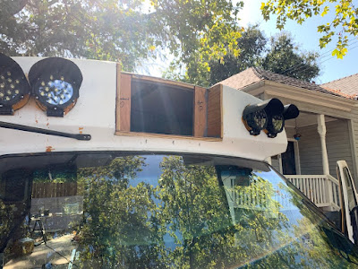
(continued from previous post)
Anyway, back to the outside. Now I installed the top panel, which follows the same procedure as the previous ones, but this was on the outside now of the slotted angle, secured using the self tapping screws.
All that was left was to replace the marker lights that I had removed. This was quite simple, as I just used a 1/2" drill bit to "widen" some of the slots on the top-forward-most angle, inserted the lights and secured them with a just a small spot of gorilla glue.
The wiring was a little more difficult, only because I really wanted to make it waterproof. So I drilled a small hole in one of the sideboards, slid some 12v wire through, then stripped and crimped the ends appropriately. Then I heat shrunk the crimps with a piece of rubber long enough to give them plenty of protection from dripping water. Back inside, I simply crimped the other end of the wire to their appropriate connections.
Lastly, I turned the air conditioner on, and felt the glorious, freezing cold air flow.
Common Gotchas
- Power supply is key. Make sure you thoroughly budget your electricity appropriately so that you can actually run this. As I have yet to do the electrics, I may end up having to add more power supply options than just solar (generator or alternator)
- Air flow and tilt. These things will overheat if they don't have enough air flow, and if they're not tilted backward, the water will drain inside
- Safety. Don't just screw this to a piece of wood. Make sure it is secured in all axis such that if you roll the bus, you don't have a 30 pound projectile flying around.
|
|
|
|
|
10-23-2019, 12:32 PM
|
#73
|
|
Bus Geek
Join Date: May 2009
Location: Columbus Ohio
Posts: 18,827
Year: 1991
Coachwork: Carpenter
Chassis: International 3800
Engine: DTA360 / MT643
Rated Cap: 7 Row Handicap
|
I like where you put the A/C unit.. unless that bus has dashboard air you are gonna be roasty while driving.. probably decently cool while parked..
how do you account for driving into the wind and running it when window A/C's blow their ar OUT the front of the condenser? you will be trying to fight the fan and either stall the air and over-temp the condenser or stall the motor and ruin it... great idea for when parked though.. looks good in that spot
-Christopher
|
|
|
|
|
10-23-2019, 12:35 PM
|
#74
|
|
Bus Nut
Join Date: Dec 2018
Location: Mt Vernon, WA
Posts: 523
Year: 1996
Coachwork: Bluebird, Collins
Chassis: G30 Bluebird Microbird, E350 Shuttle Bus
Engine: 1995 Chevrolet 350, 1992 Ford 460
|
Nice work. Really good documentation too. Thanks.
|
|
|
|
|
10-23-2019, 12:40 PM
|
#75
|
|
Bus Nut
Join Date: Apr 2018
Posts: 421
|
Yeah I don't have any dash air. At all. No heater or fans or anything.
I've thought about the fan issue, and since I can't ops test it for a while (the electrical is still far out), I'll have to wait. Three potential solutions:
- Install a plate cover that goes over the front grille to disrupt the airflow while driving (perhaps something that covers the sides or top as well to appropriately direct the air)
- Disassemble the unit, find the positive wire for the fan, reroute that wire to a switch over the driver's seat, where I can turn the fan on or off depending on if I'm driving
- Worst case scenario, the A/C will only be available when parked (which is still better than now)
The fun thing is that I didn't even think of that issue until after I had installed it. This isn't the first time my all-thrust-no-vector enthusiasm has gotten me in trouble.
|
|
|
|
|
10-23-2019, 12:49 PM
|
#76
|
|
Bus Geek
Join Date: May 2009
Location: Columbus Ohio
Posts: 18,827
Year: 1991
Coachwork: Carpenter
Chassis: International 3800
Engine: DTA360 / MT643
Rated Cap: 7 Row Handicap
|
that bus surely wasnt built with no dashboard heaters... is it just that the dashboard system doesnt work? the van chassis itself came with heaters and heater controls.. that factory.. whether it originally had a dashboard A/C is anyone;s guess (if it says A/C on the dial pretty much)..
onto your window unit, the other thing to think about is most window units have an outside vent.. it can usually be opened or closed by a knob or lever on the unit.. that typically has not much more than a plastic flap connected to a cable with no super seal on it.. if the unit has this, it will possibly be a rain magnet for water to get in.. if it has this.. tape over it with flex-seal-tape or such.. you dont really need it..
next is that unless thats a pretty fancy unit, most have one motor that drives a blade fan on the outside and through use of a double shaft drives a centrifugal blower on the insider.. turning off the motor turns off the inside fan too.. if you are luck you have a unit with 2 fan motors and killing the outside motor while moving would be possible..as long as you didnt stop at a red light and forget t oturn it back on.. .. they exist but are usually the high end pricey ones..
|
|
|
|
|
11-01-2019, 01:02 PM
|
#77
|
|
Bus Nut
Join Date: Apr 2018
Posts: 421
|
How to Install the Floor in a Skoolie
Planning the Subfloor in a Skoolie
The more insulation, the better--but also the less head room. Unfortunately for me, I already can't stand in the bus, so that doesn't really matter. However, the ribs in the bus along the walls and ceiling are about 1" thick, meaning if I got 1" thick insulation, it would form a flush surface on which to mount the walls and ceiling later--so I opted for 1" thick insulation on the floor too just to make it easy.
I also wanted to have a wire conduit running under the floor, such that I wouldn't have to run wires across the floor or ceiling where they'd be visible. This is what the 3/4" PVC pipe is for, as it's outer diameter is 1.05", meaning I can put it in instead of insulation, then cover it all with the plywood. I also did this with the fresh water lines, where they run through the insulation and under the plywood floor.
It was important to have big, solid chunks of plywood for the seating area where the seatbelts will be (for structural integrity), as well as for the walkway (to prevent any floor "creaking"). These would be the first pieces of plywood I'd put in.
Lastly, the portion of the floor under the seating area would be "floating" meaning it won't have any wall or ceiling attachments. This is obviously a problem, as if the bus rolled and came to a rest upside down, the floor would fall under my passengers, who would be held up by the seatbelts. So I need to secure this part of the floor to the actual floor.
One final note: all the holes should already be patched with fiberglass (see my previous post about this), and the floor should be painted. My floor is made of aluminum, so I'm not too concerned about corrosion if water sneaks in, but I gave it a single coat of paint (the same paint I used for the outside).
How to Frame the Subfloor in a Skoolie
Essentially, anywhere the side of the floor would be exposed (the front stairs and the back door), I installed strips of 2 x 4's to sort of "frame" the floor in. Parts of this floor were sloped and uneven, so I used a few extra scraps of whatever I could find to level it out, and used a small amount of expanding foam to lock them in place. This is the only framing I have for the floor.
Installing Floor Insulation in a Skoolie
This was the easiest step. I simply measured and cut the insulation to cover the entire floor. It's worth mentioning that since the bus walls are curved, this changes the dimensions of the usable floor area now that we're 1" higher than the actual sheet metal floor of the body.
Once the insulation was in, I used a router to notch the insulation for my fresh water lines, which can be described in more detail in my water pump post. I also made sure there was space for the PVC electrical conduit, and I preinstalled three two-wire strands in there, as well as a string runner for future installation of any more wires.
Those plumbing fixtures are in anticipation for both the sink that will drain straight down into the tank, as well as draining the fluid from the composting head. The Hepvo traps will not actually go under the floor. The clear tubing is the vent for the grey tank, which will be attached to the vent for the composting head as well. See? You gotta plan ahead!
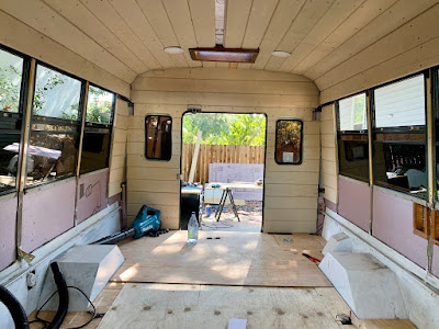
Installing a Plywood Floor in a Skoolie
Now things get interesting. I started with the seating area, which is the aft end of the bus. I wanted this piece to be as solid as possible, which was easy because the bus is approximately 6.5' wide, and these sheets of plywood are 8 feet long. So I turned one sideways and cut it to 6.5' long. I also had to cut out notches for the wheel wells, the fuel intake, and also a hatch I had created for the propane tank. This required a good amount of trial and error, because like I said earlier, the dimensions changed a bit now that the 1" thick insulation was in.
Once I got it to fit, I patched up the empty areas around the edges with extra pieces of plywood and used duct tape to hold them in place for the time being.
Next, I installed the other massive single piece, which was for the walkway. Again, I had to measure and cut out the notches for the framing I installed earlier, and I actually ended up having to use the router to make a notch on the underside of the plywood to accommodate the extra .05" height of the PVC pipe.
The remaining areas that needed to be installed also had their own unique challenges--on the right side, I had to cut an open area for the water intake lines, and for the other side, I had to do the same for the plumbing for the sink and head drain. Perhaps if you just look at the photos it'll make more sense.
Securing a Floating Floor in a Skoolie
The last step was to bolt the floor to the floor. I only did this with the aft end of the bus, with that big piece that will go under the seats, because the other one will be secured to the walls and ceiling. I used 3/8" bolts and the Simpson Strong Tie Metal Straps. These were bolted through the plywood, insulation, and sheet metal floor, and secured with locking washers underneath the bus.
Common Gotchas
- Dimensions change the higher off the floor you go. Adding an inch of insulation added about an inch on each side for the plywood from my original measurements
- Securing the floor where folks will be sitting is key for safety in my opinion. Busses have great roll safety but if it comes to rest upside down, the floor will come down too
- Planning ahead for wiring and plumbing. I don't know exactly where the batteries will sit, or the inverter, but the conduit under the floor will make it super easy to run wires across sides of the bus
|
|
|
|
|
11-02-2019, 12:39 AM
|
#78
|
|
Member
Join Date: Apr 2019
Location: Middletown, Oh
Posts: 12
Year: 2011
Coachwork: International Aero Elite
|
vapor barrier
My bus is a fiberglass shuttle bus. Do you think I need to worry about a vapor barrier w, h my insulation job.
By the way, I love your bus and I'm learning a lot just by following you.
|
|
|
|
|
11-02-2019, 01:48 PM
|
#79
|
|
Bus Nut
Join Date: Apr 2018
Posts: 421
|
Keep in mind Im a total amateur here, but in my opinion you probably dont need a vapor barrier. Fiberglass is much more inert to water condensation than metal, but then again if you have a wood core and water gets in there its the end of that patch of fiberglass. But if you dont have a wood core I wouldnt bother with the extra weight and time to and money to install. I opted for no vapor barrier because mine is aluminum and I live in a very dry climate and I figured a single coat of paint ought to be good enough.
|
|
|
|
|
11-09-2019, 09:57 AM
|
#80
|
|
Bus Nut
Join Date: Apr 2018
Posts: 421
|
How to Install the Insulation, Walls, and Ceiling in a Skoolie
Similar to the floor, I installed the insulation first and then the wood. Unlike the floor, however, I did this piece by piece, installing insulation in one portion, immediately followed by the wood for that portion. The hardest part was cutting the wood to fit the weird corners and curves.
I started in the back and worked my way to the front. The key here is to cut strips of insulation in order to fit the curved corners, and ensuring that the wires are sufficiently flush with the insulation such that they form a flat surface on which the wood can be installed.
One thing I wish I would've done is instead of measuring once and cutting a bunch of boards for that section, I should've measured the specific length of each board and then cut them individually. This would've saved me a lot of cosmetic pain later.
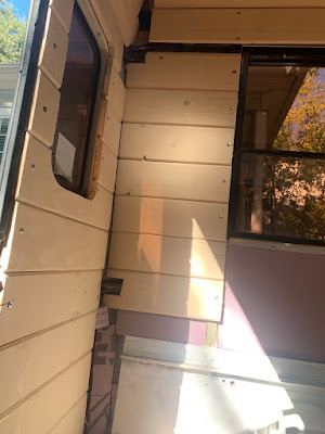
Anyway, I'd put up a panel of insulation with the foam board adhesive, then cover it with the shiplap. Then I'd move up and repeat, covering the entire back wall first before moving on to the ceiling. At first I used the self tapping screws to attach the shiplap to the ribs, but the screws were a little too short and they sucked at tapping through the metal. So then I switched to predrilling the holes with a bit and using either the self tapping screws or the construction screws. Here again I wish I would've used the proper screws for metal, not the construction screws, but now you can learn from my mistakes.
Once the back wall was installed, I ops tested the lights to make sure I hadn't accidentally drilled through one of the wires. They all worked so I moved on to the back side walls, and when they were done I moved on to the ceiling.
Something to note here is that I insulation everywhere, but only used the shiplap where there would be no bench seating or cupboards. I did this to save on weight and materials.
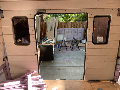
I ended up replacing the bottom portion of the shiplap in the above picture (the portion that would be under the bench seating) with 3/4" plywood to be a backing for cargo carriers hanging off the back of the bus.
For the ceiling, I had to route conduits for the ceiling light wires, and install the lights as I went. Fortunately the lights I used were approximately the same width as a shiplap board, which made the installation pretty straight forward.
Installing the ceiling boards was a huge pain because I'd have to hold one up, tap the hole with a bit, then drill the screw in, and go to the other end of the board and repeat, all the while holding the board up. This strained my shoulders quite a bit. I should've gotten a partner to help, as it would've saved me a lot of pain and time.
For the ceiling, I opted to start right above the windows on each side and work my way up, where they'd meet in the middle of the bus leaving an irregular gap between the last two boards. Instead of cutting a shiplap to fit this gap, I used 1/4" plywood to fit in between.

The most difficult part was the front of the bus, because of the weird angles and hardware. The bus door handle hinge needed to move freely. The air conditioner stuck out. And I wanted cabinets up there for more bus related things such as registration, oil, and tools. The ceiling was easy all the way forward, but then the "wall" portion took a lot of measure-cut-fit-repeat to get it to work.
I first installed the "floor" of the forward upper cabinets by cutting multiple pieces of plywood to fit the curved top edge of the chassis. This was a huge pain because of just how much it curved in three dimensions. Next, I built up the walls above that, including insulation the air conditioner "box" and installing plywood over that. It's important to note that I didn't install insulation everywhere--I wanted the extra storage space, and figured that the cabinetry and its contents would provide enough of a thermal gap to insulate. Finally, for the front "faces" I cut out the cabinet doors, installed the doorless face, then made some really simple hinges and a knob.
For the rest of the weird areas that didn't quite get covered, such as the aft end of the ceiling, I used 1/4" plywood to cover up the gaps.
Commons Gotchas
- More insulation is great, but consider the loss of headroom
- Get a buddy to help install the ceiling; you'll appreciate it
- Self tapping screws are great, but I found they didn't tap very well into the ribs, so I had to pre-drill the holes myself (and I went through three drill bits). Also I wish I would've used proper sheet metal screws instead of construction screws, so as to make sure it was a better connection
|
|
|
|
|
|
| Thread Tools |
|
|
| Display Modes |
 Linear Mode Linear Mode
|
 Posting Rules
|
You may not post new threads
You may not post replies
You may not post attachments
You may not edit your posts
HTML code is Off
|
|
|
|
 » Recent Threads
 |
|
|
|
|
|
|
|
|
|
|
|
|
|
|
|
|
|
|
|
|
|
|
|
|
|
|
|
|
|
|
|
|
|
|
|
|
|