Journey with Confidence RV GPS App RV Trip Planner RV LIFE Campground Reviews RV Maintenance Take a Speed Test Free 7 Day Trial ×


Reply
 
Thread Tools Display Modes
 
Old 08-10-2016, 03:44 PM   #1
Skoolie
 
Justin McCormick's Avatar
 
Join Date: Jun 2016
Location: Texas
Posts: 160
Year: 1997
Chassis: Saf-T-Liner MVP ER
Engine: Cummins 5.9L Diesel Engine
Rated Cap: 83
Installing a kill switch on the starter battery bank

I want to add a kill switch to the starter batteries. Bellow is a diagram of how I want to set it up, and has hoping to get some feedback on it to make sure I am setting it up correctly.
The batteries are 12volt so should be wired in parallel. The wire as noted in the diagram are 4/0 AWG. I was thinking of getting this switch for the setup.


Justin McCormick is offline   Reply With Quote
Old 08-10-2016, 04:54 PM   #2
Bus Crazy
 
sdwarf36's Avatar
 
Join Date: Oct 2009
Location: Moodus, Ct.
Posts: 1,062
Year: 1996
Coachwork: Champion
Chassis: Ford e-450
Engine: 7.3 Powerstroke
Rated Cap: 14
Boat part= expensive. Race car part=alot cheaper.

JEGS Performance Products 10375 | Buy JEGS Water-Resistant Master Battery Disconnect Switch at JEGS
__________________
Don't make a fuss-just get on the bus!

my bus build https://www.skoolie.net/gallery/Skoolies/Sped
sdwarf36 is offline   Reply With Quote
Old 08-10-2016, 05:20 PM   #3
Bus Crazy
 
somewhereinusa's Avatar
 
Join Date: Nov 2010
Location: Andrews,Indiana
Posts: 2,437
Year: 1991
Coachwork: Bluebird
Chassis: AARE
Engine: 3116 Cat 250hp
Rated Cap: Just the two of us.
The o.o link is to a dual circuit switch, do you need that? It is also rated for 350A which is good if you need it. The second one is only rated 100A continuous. I would disconnect the positive side.
somewhereinusa is offline   Reply With Quote
Old 08-11-2016, 09:36 AM   #4
Skoolie
 
Justin McCormick's Avatar
 
Join Date: Jun 2016
Location: Texas
Posts: 160
Year: 1997
Chassis: Saf-T-Liner MVP ER
Engine: Cummins 5.9L Diesel Engine
Rated Cap: 83
Quote:
Originally Posted by somewhereinusa View Post
The o.o link is to a dual circuit switch, do you need that? It is also rated for 350A which is good if you need it. The second one is only rated 100A continuous. I would disconnect the positive side.
The one I was planning on getting was the single circuit (there are selection options on that page)
Not sure how to tell what Amps I need, so figured I would go hight just to be safe.
Is there a benefit to disconnecting the positive over the negative? I have noticed that the studs are 3/8 on the switch indicating that its designed for the positive cable.
Justin McCormick is offline   Reply With Quote
Old 08-11-2016, 11:36 AM   #5
Bus Geek
 
ol trunt's Avatar
 
Join Date: Apr 2012
Location: So Cal
Posts: 3,231
Year: 1935
Coachwork: Superior
Chassis: Chevy
Engine: 317 ci/tid / Isuzu
Good post. I'd never given much thought as to which battery post to put a cut out switch on. I guess I'd just assumed it should go on the +tive. Now that I've done some research I can see logical reason for switching the -tive. While I'm far fron being an automotive electrical engineer, the following video seems to be pretty convincing in it's recommendation for -tive switching--particularly the portion showing the terminal size difference. I guess ya pays ya money an takes ya chances!?! Jack
ol trunt is offline   Reply With Quote
Old 08-11-2016, 05:50 PM   #6
Bus Crazy
 
sdwarf36's Avatar
 
Join Date: Oct 2009
Location: Moodus, Ct.
Posts: 1,062
Year: 1996
Coachwork: Champion
Chassis: Ford e-450
Engine: 7.3 Powerstroke
Rated Cap: 14
I'm used to installing kill switches -like the one I posted - in race cars. Done very many. They are always on the positive side.( To the point where most have a smaller secondary kill for the altenantor power.) Which I've questioned why. I mounted mine on the neg side. Never seen any rules that said it must be one way or the other. Only thought i ever go was "in the neg wire falls off, it COULD make ground against the cage/floor/something."
__________________
Don't make a fuss-just get on the bus!

my bus build https://www.skoolie.net/gallery/Skoolies/Sped
sdwarf36 is offline   Reply With Quote
Old 08-11-2016, 06:36 PM   #7
Bus Nut
 
Join Date: Oct 2011
Location: Snowflake, Arizona
Posts: 343
Year: 1996
Coachwork: Blue Bird
Chassis: All American Rear Engine
Engine: C-8.3-300 Cummins MD3060
Rated Cap: 40 Prisoners
If you check the amperage carrying capacity of 4/0 cable you will find
that your battery disconnect switch will be the weak link in the system.
I would suggest as a minimum a switch with 500 amp capability and
1000 amp momentary rating. The suggested one from summit racing
is only capable of handling the output from the alternator and nowhere
near adequate for starting a diesel engine of bus size. Overkill on the
amperage carrying capacity of a disconnect switch should be the order
of the day.
Dragonpop is offline   Reply With Quote
Old 08-11-2016, 07:05 PM   #8
Bus Crazy
 
Join Date: Feb 2012
Location: Salt Lake City Utah
Posts: 1,635
Year: 2000
Chassis: Blue Bird
Engine: ISC 8.3
Starter current is something I've wondered about, too. In my case the engine is a Cummins ISC 8.3L. I've seen the occasional bit of information calling out this starter as a 6.4 kW unit (there for example). Supposing the battery drooped to 10 volts while cranking, it would be in the neighborhood of 640 amps if the starter really pulled that rated 6.4 kW. But I don't know whether that would be "normal" or whether it's merely the maximum limit of the motor and we'd normally crank at a much lower current. I suspect the latter. So is normal 300 amps? 500? I'd love to see some data.

Interesting points made about switching positive side vs negative side. Here's another to consider. Virtually everything conductive in the area of the battery is connected to the body ground. Suppose one disconnects the negative cable before beginning work. If a metal tool is dropped and it bridges from a battery terminal (either terminal!) to some surrounding metal, it's no big deal. Either the tool connects the body to the positive terminal, which is fine because the negative terminal is disconnected so no current flows, or the tool connects the body to the negative terminal, which is also fine because that's what will eventually happen anyway when the battery lead is put back on. Accidental shorting either terminal to the body, engine parts, brackets, etc is safe. On the other hand if the positive were disconnected and the tool dropped, there's a 50/50 chance it'll be shorting the positive terminal to the body, which is wired to the negative terminal, and Bad Things may ensue.

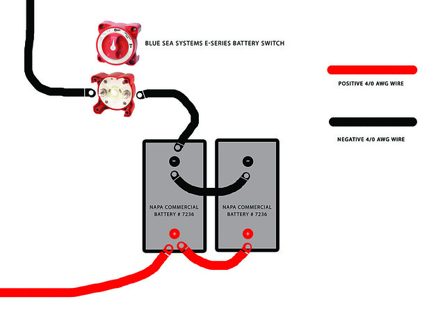
A note about the original wiring diagram: it's slightly superior to take the positive lead off the post on one battery, say the one on the left as drawn, and take the negative lead off the post of the battery on the opposite end of the chain (ie the right side). This ensures the batteries will be equally loaded. When connected as in the diagram, that battery on the left will carry more of the starting burden than will the one on the right because of the extra resistance of the cables and clamps going to the battery on the right.
family wagon is offline   Reply With Quote
Reply


Posting Rules
You may not post new threads
You may not post replies
You may not post attachments
You may not edit your posts

BB code is On
Smilies are On
[IMG] code is On
HTML code is Off
Trackbacks are Off
Pingbacks are Off
Refbacks are Off


» Featured Campgrounds

Reviews provided by

Powered by vBadvanced CMPS v3.2.3

All times are GMT -5. The time now is 04:29 AM.


Powered by vBulletin® Version 3.8.8 Beta 4
Copyright ©2000 - 2024, vBulletin Solutions, Inc.