Whoa, I totally glazed over the battery hookup drawing. Thanks for catching that Steve.
Even looking at it 3 times, my eyes keep crossing.
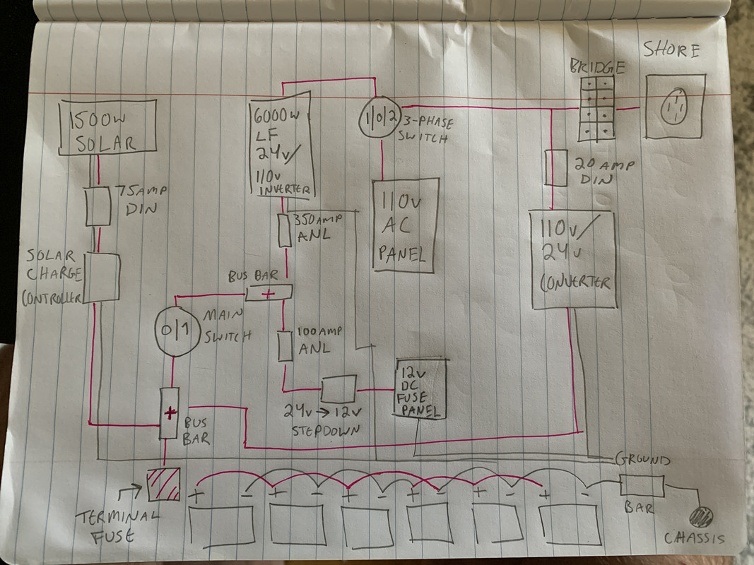
You might want to re-draw that section a bit so it is a little less confusing. I'm not sure you are ending up with 2 series by 3 sets parallel in that drawing, which I assume is what you want since it's all 24V specced.
Here's is how I would hook it up:

If you draw it out that way, and think of it that way, it'll help you when you lay it out that way for installation. It's the most efficient layout for cable lengths.
In terms of the rest of your diagram, the "ground bar" and "bus bar w/terminal fuse" are natural places to break your schematic. Treat the battery side as its own schematic and keep it as simple as possible. The the other side starts at the battery connection terminals on the ground bar and bus bar terminal fuse.
I'm sorry I missed that the first time through. You don't show where the wire connects from the terminal fuse to the batteries but the assumption would be the red line, which if you follow it, leads right on over to the ground bar.
When you're talking that many batteries with that much capacity, you want to guarantee there's no chance of shorting anything out, so take the time to draw it as simply as possible. I do like that you used red ink. Also, I'm assuming you're chaining 12V batteries. You should specify the voltage on the battery diagram for each battery.


 Linear Mode


